FAC system 3 gripper Rubik's Cube Solver
Contents
Inspired by cube solvers made with Lego and Fischer Technik, I started this project in the later part of 2009 and it was (for several reasons) not until the summer of 2015 before I finished this project.
This cube solver is entirely made with FAC system parts. The machineconfiguration is after a design by Wilbert Swinkels whilst the programming part was done by the gifted Maxim Tsoy. An important collaborator regarding the project as a whole was Toto van Inge, member of the University of Amsterdam, Faculty of Science.
After a long proces, we finally made the machine working, see the following video. We made use of the Kociemba code regarding the solving algoritm.
We are working on a second generation FAC system Cube Solver, containing 4 grippers, color recognition by a Raspberry Pi camera and an entirely newly designed gripper.
Mechanical design
First concept
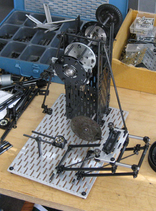
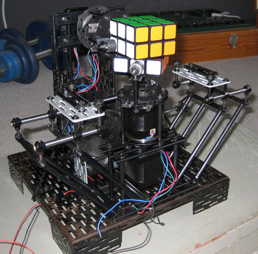
The first concept was based on 2 grippers as can be seen below. This model however has never led into an operational cube solver, as it soon became clear to me, that the cube most likely wouldn’t be kept properly into it’s position by the grippers.
The pictures below are all from September 2009.
Second concept
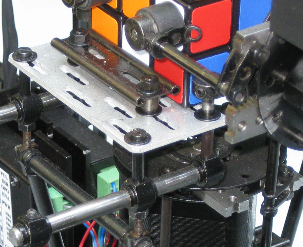
By the mid of October 2009 an extra gripper was introduced in a newly built model. The table which positions the cube in relation to the grippers proved to be a reliable construction and was for this reason adapted into the second design.
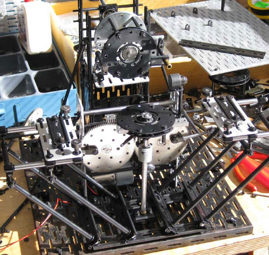
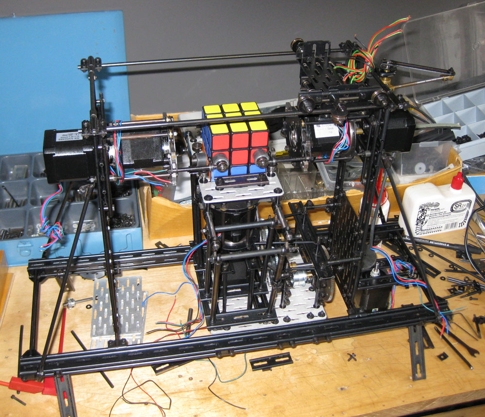 Cube solver as per October 2009
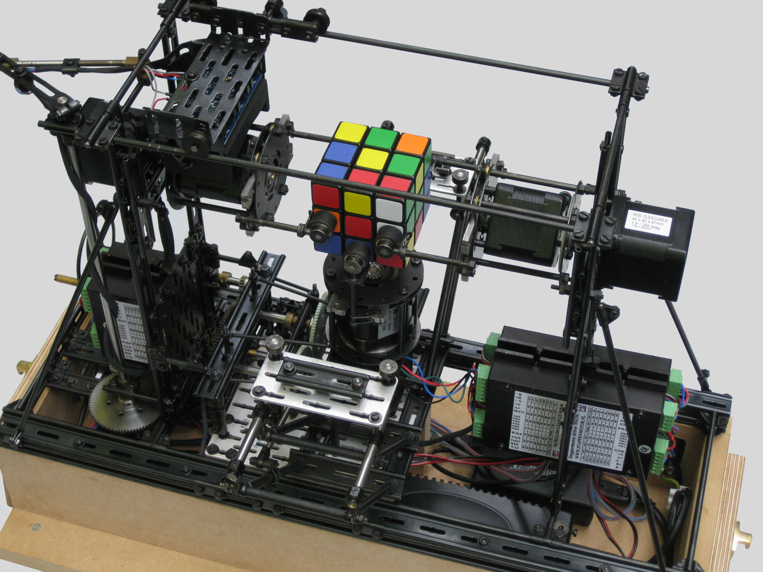
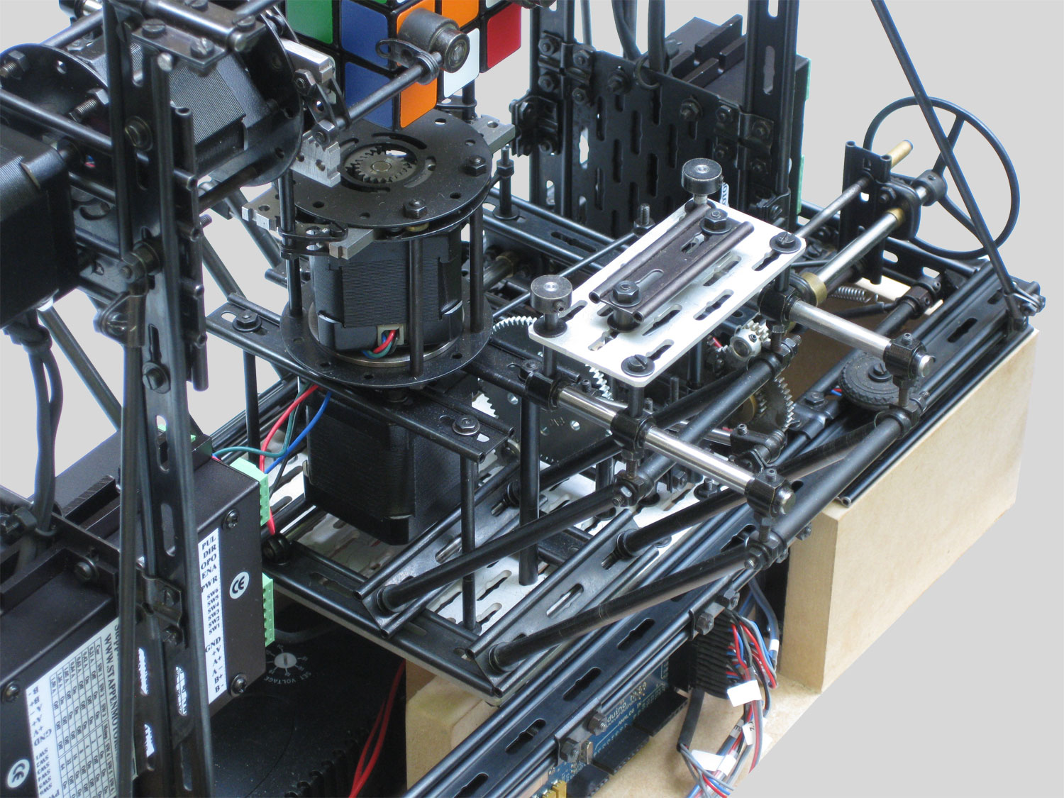
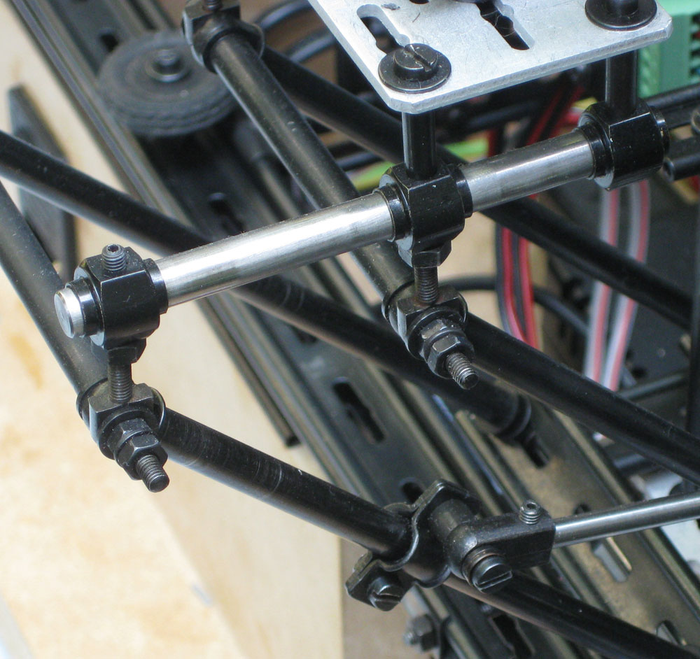
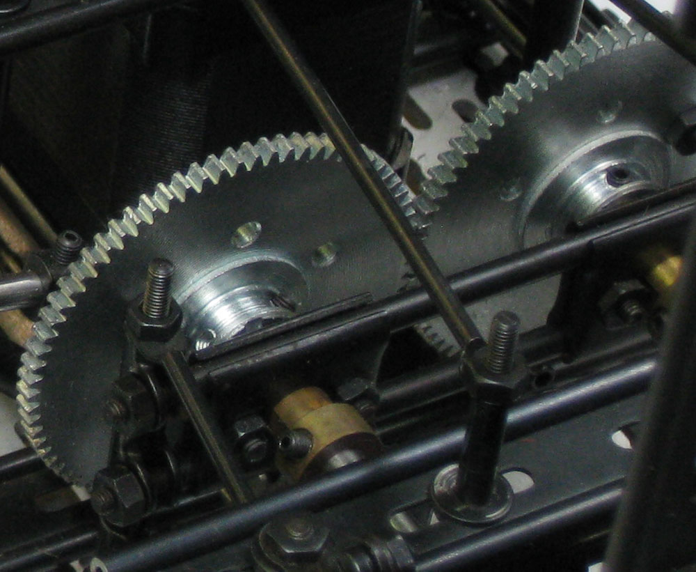
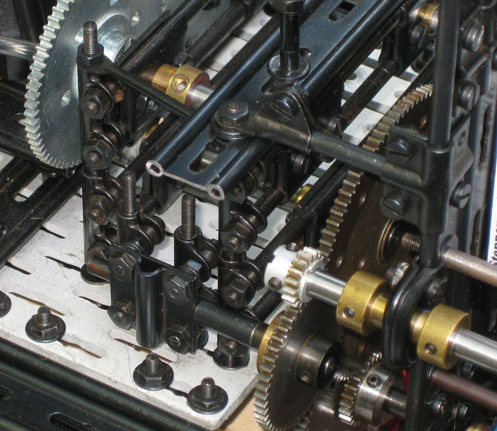
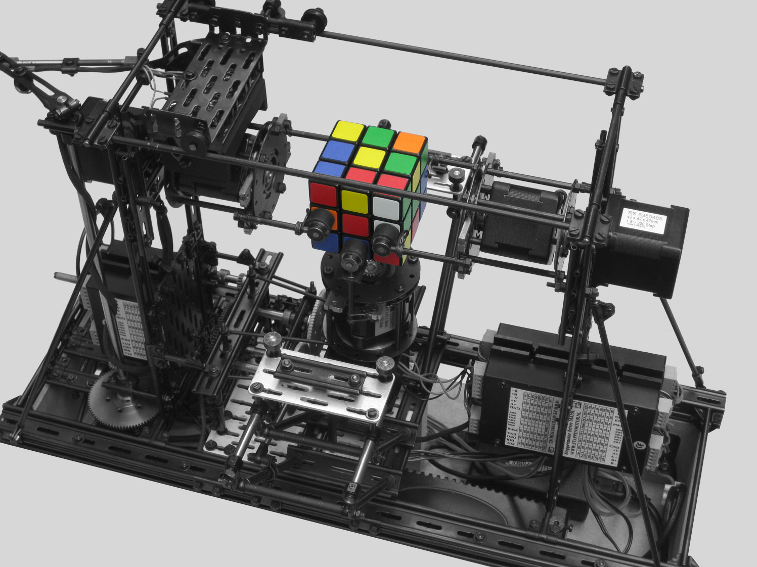
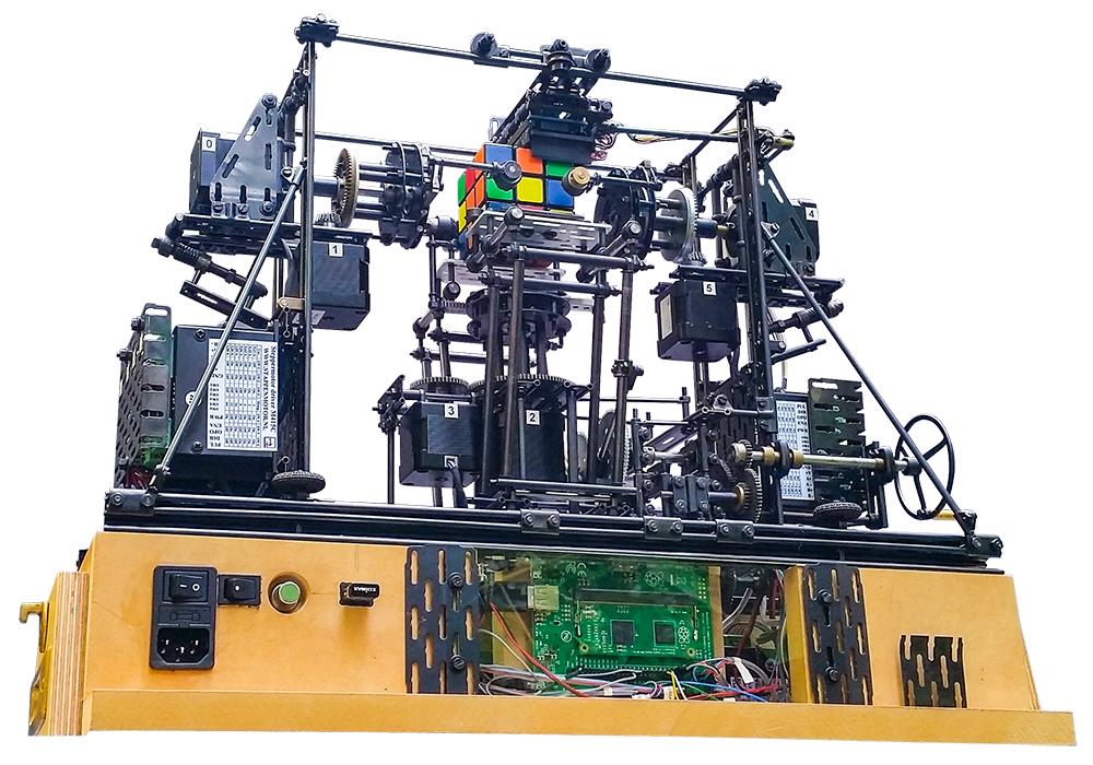
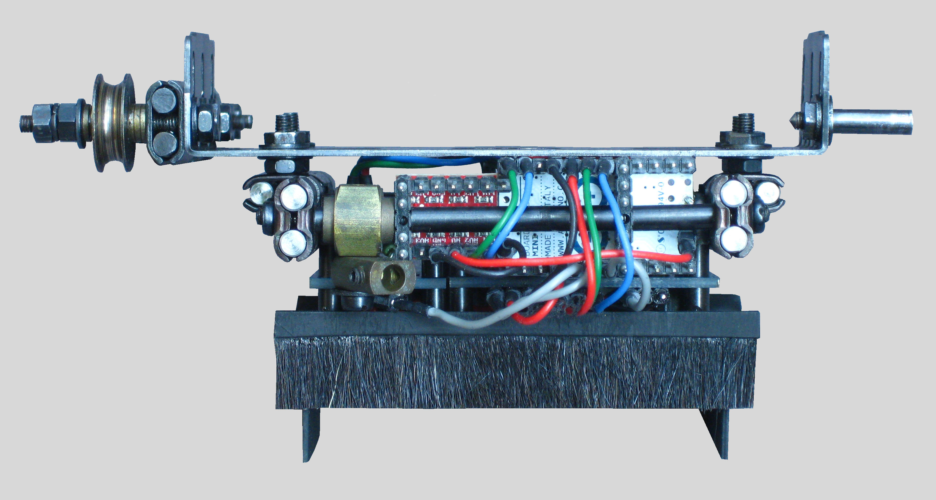
All the frame forming parts, the gearing system an other mechanical elements are FAC system parts. Both the 4 and 6mm axles were used and if necessary shortened on a mini lathe. Several triangular shaped structures were constructed to achieve a statically determined frame. All non FAC system modules (steppermotors, drivers, colorsensors) have been incorporated within this frame. The slotted holes of the parts, one of the characteristics of the FAC system, makes the mounting of the aforementioned modules very easy.
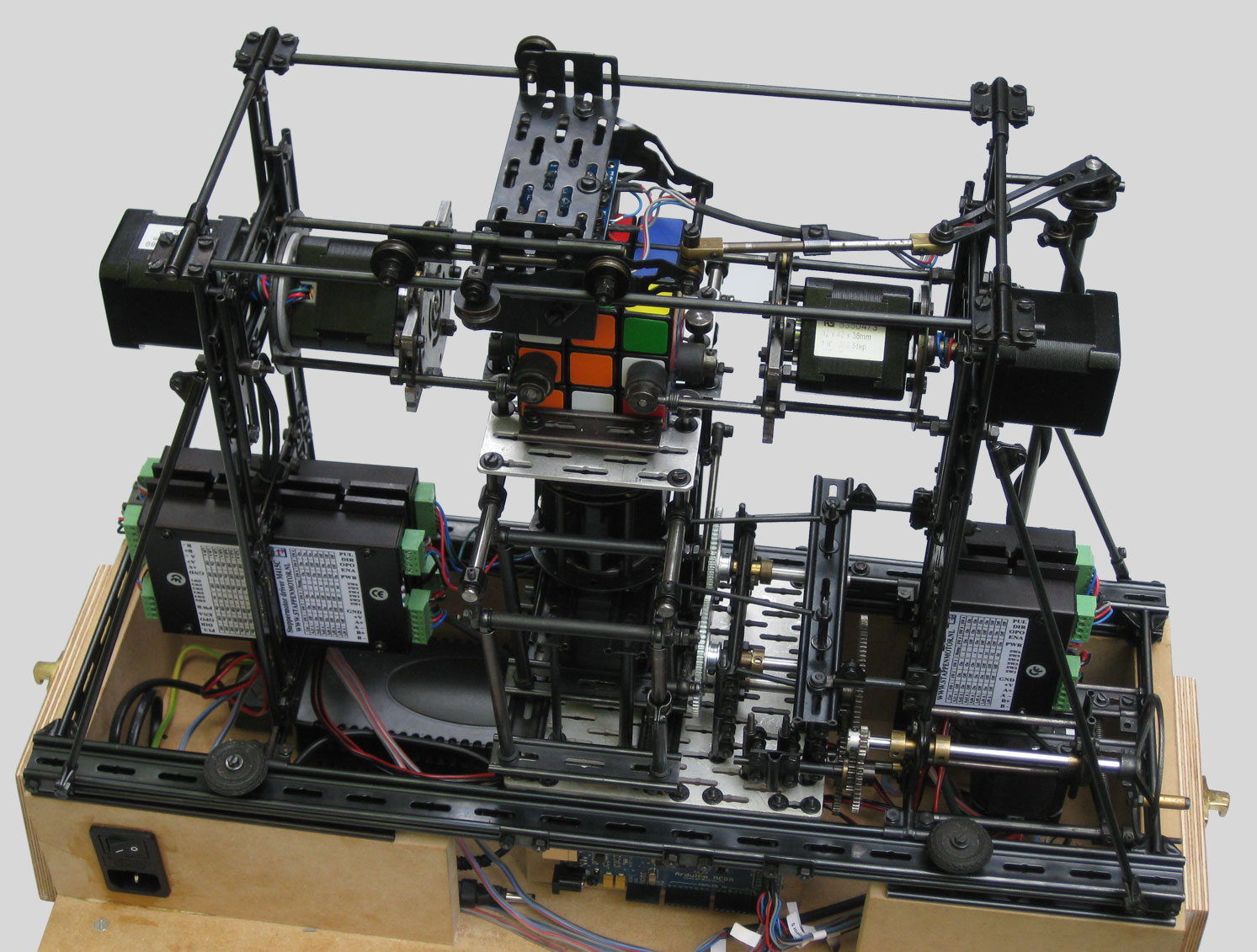
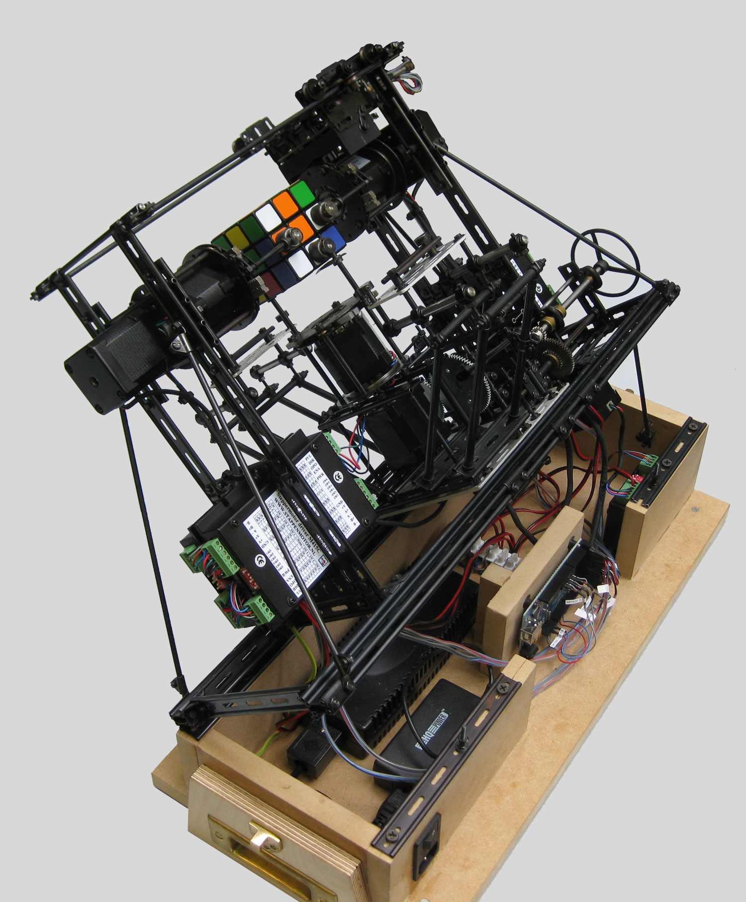
The total construction is mounted on a MDF basement, in which all the required electric components are housed. A wooden box can be placed on top of the basement to close the model and make it ready for transport. Once, when the model has found it’s destination at several exhibitions throughout Holland the toplid of the box can easily be removed and the model is ready for a demonstration. The pictures below were all taken in July 2010.


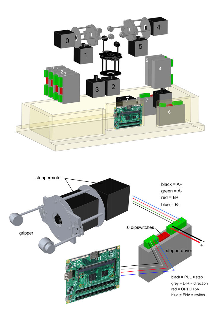
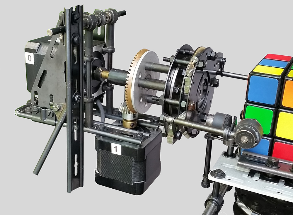
Motors, motordrivers and grippers
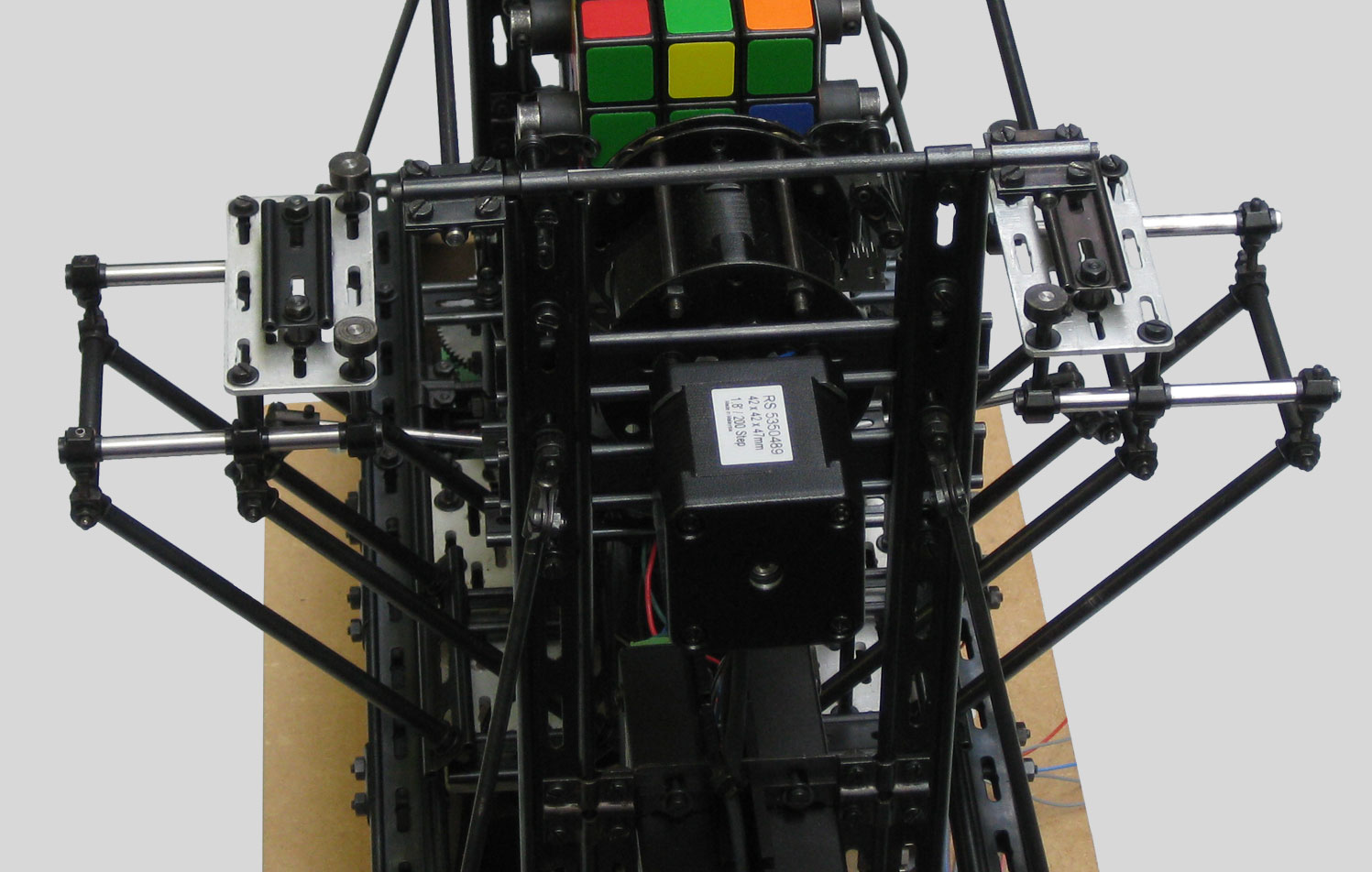
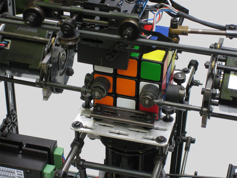
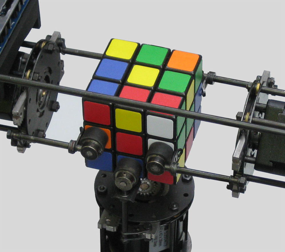
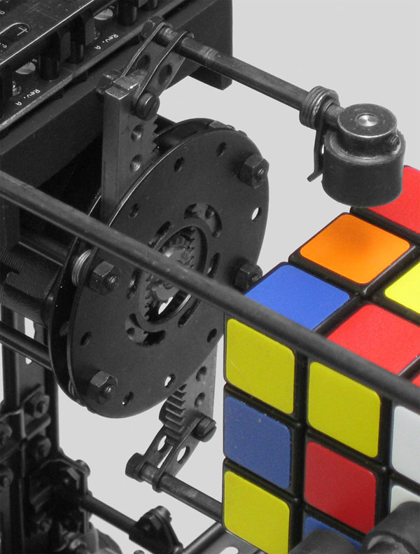
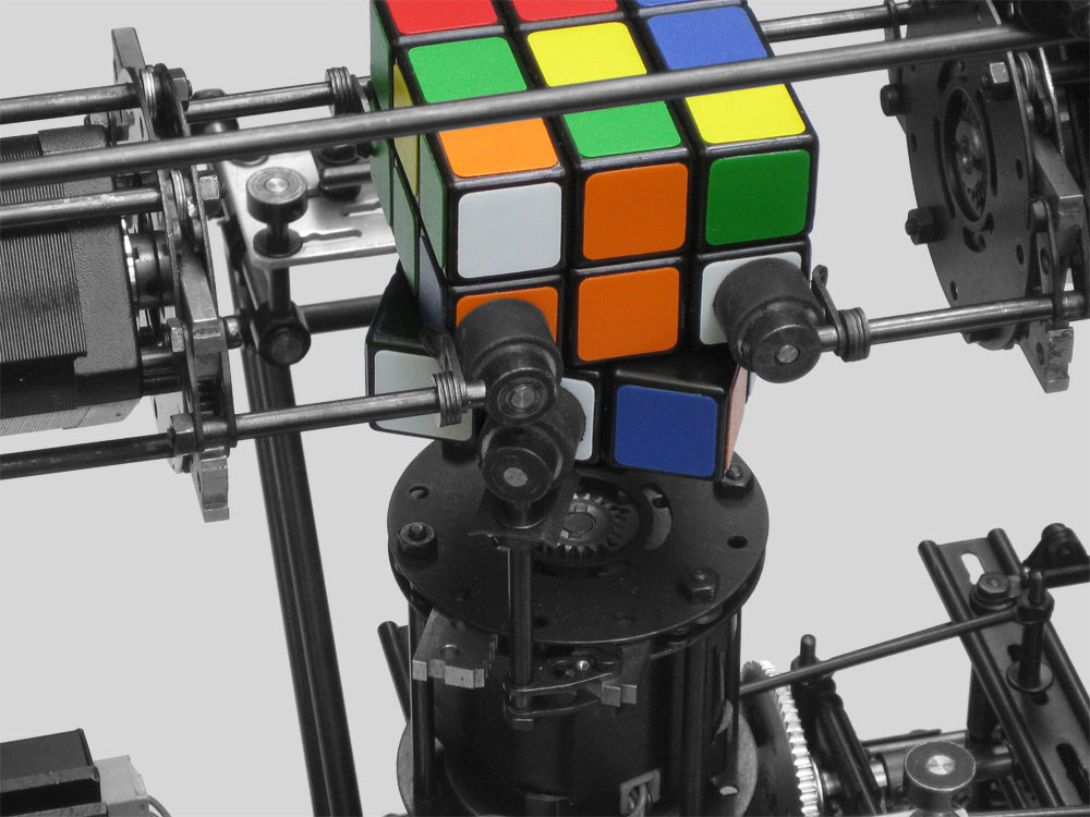
The cube solver incorporates 3 grippers to grip the cube and to keep it in it’s position. It’s evident, that this device must be perfectly aligned, otherwise the rotating proces migth lead into a malfunctioning system.
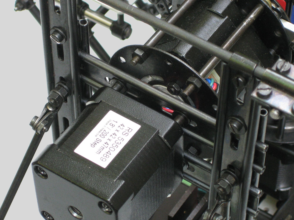
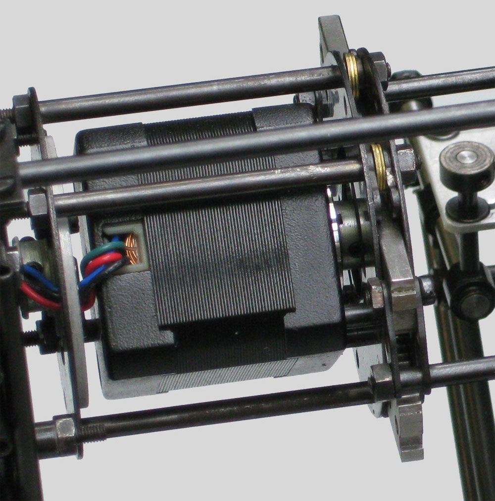
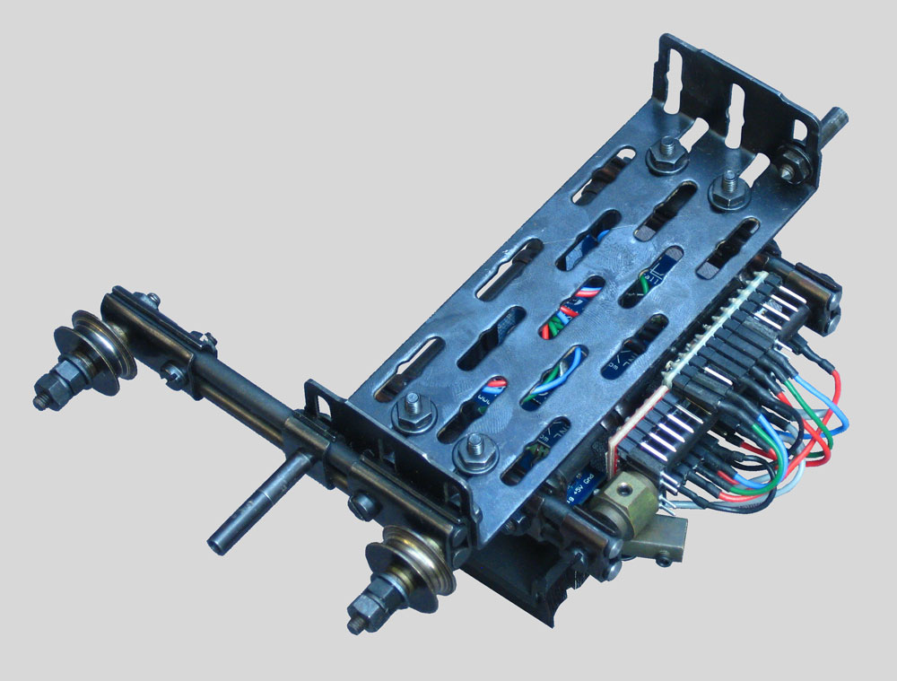
Each gripperdevice excists of 2 motors: one motor drives the gripping and is incorporated within a satellite, which has been mounted on the rotor of the second motor. The second motor is fastened on the frame of the rigid construction.
A stepperdriver is needed to proces the generated commands from the Raspberry Compute Module to the motors. The stepperdrivers and motors I used are of a bipolair type, are worldwide available (if you stick to standard motors).


Some photoshopped promotional pictures (machineconfiguration of 2010):
It must be mentioned, that in the later part of 2010 it became clear, that the concept of the gripperdevice could be improved.
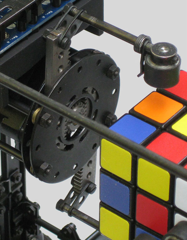
In the original gripperdesign one motor was mounted within the satellite of the gripper, whilst the satellite itself was mounted on the rotor of the second motor:
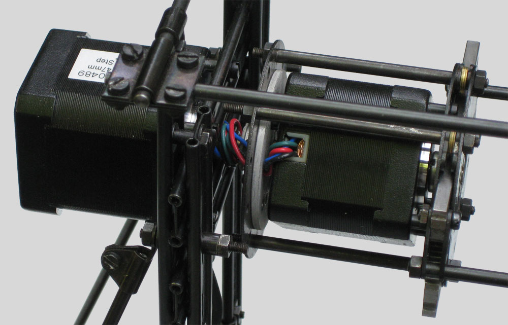
It worked, but obviously the freedom of rotation of the satellite was limited, because the wiring of the satellitemotor cannot rotate endless into one direction. Although this could be solved on the programmerside, there is another reason to ouplace the motor, namely the inertia of the rotating device. The more mass a rotating object has the more force you need to get it rotating, speed it up and stop it again.
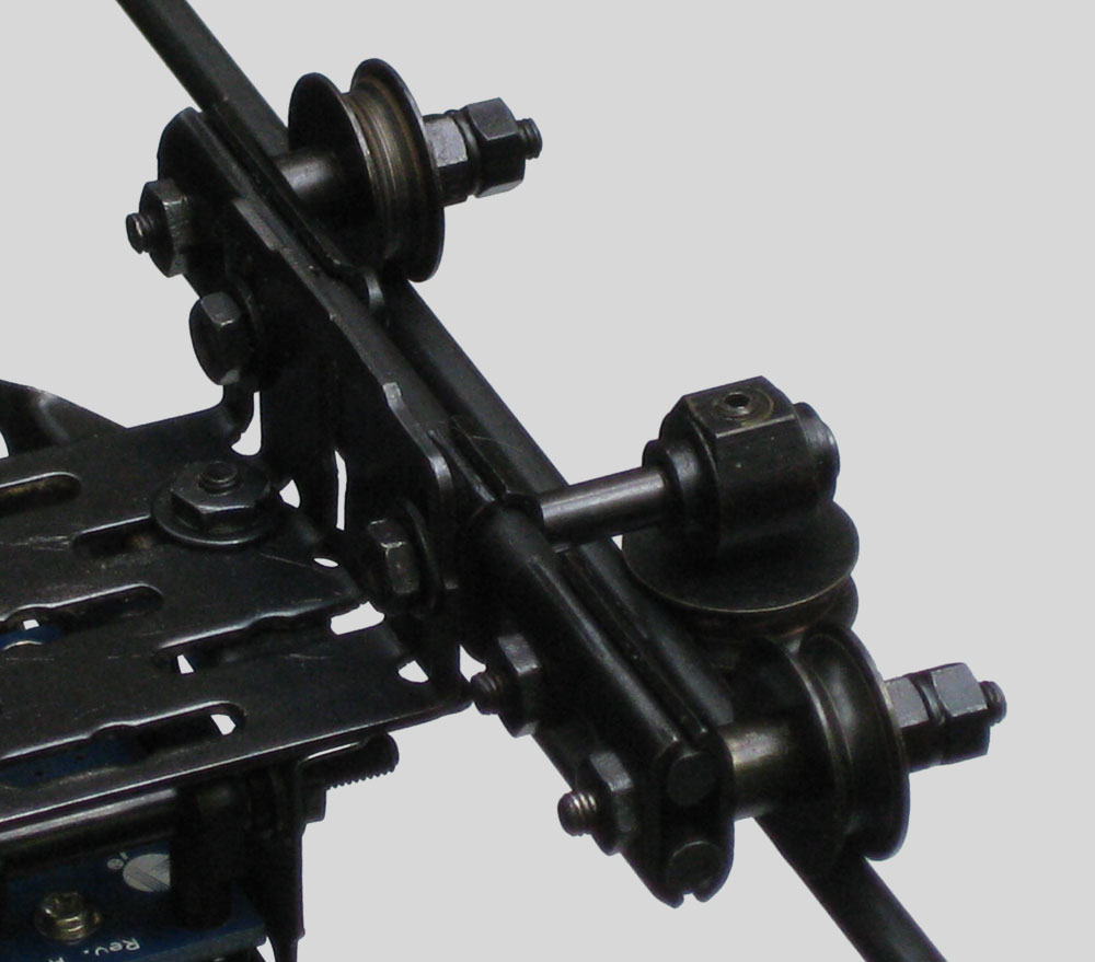
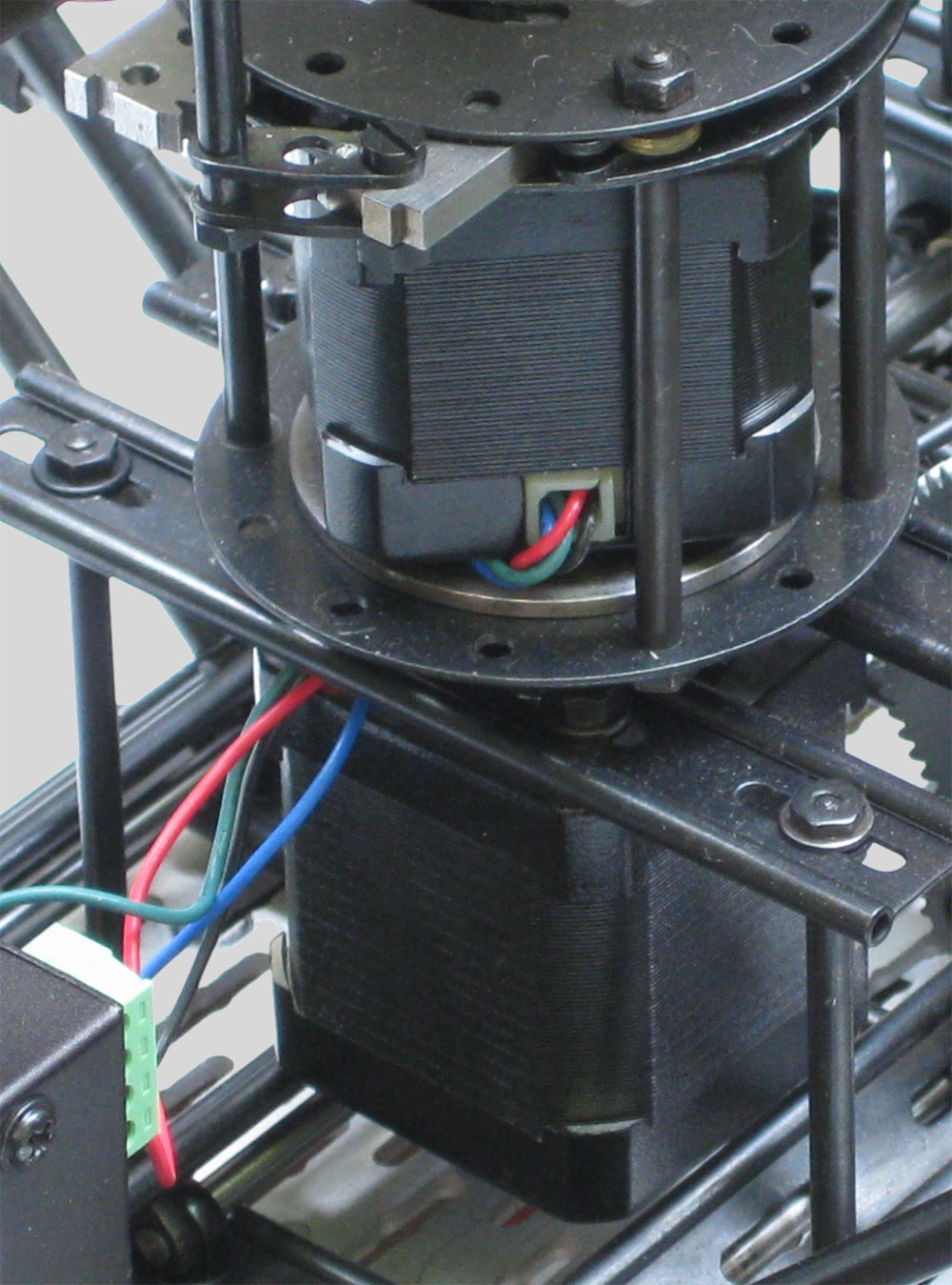
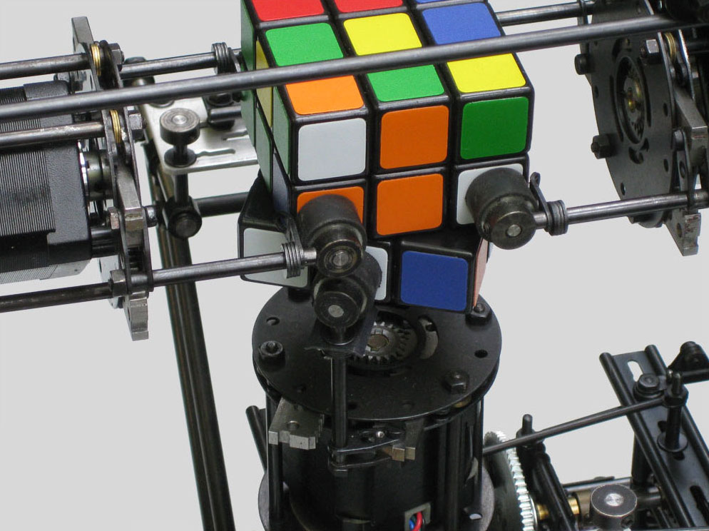
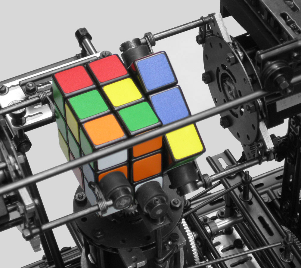
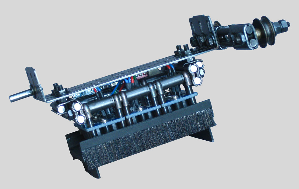
For these reasons I decided to modify each gripper device conform the following configuration:
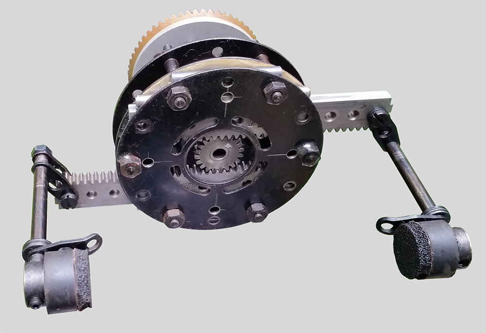
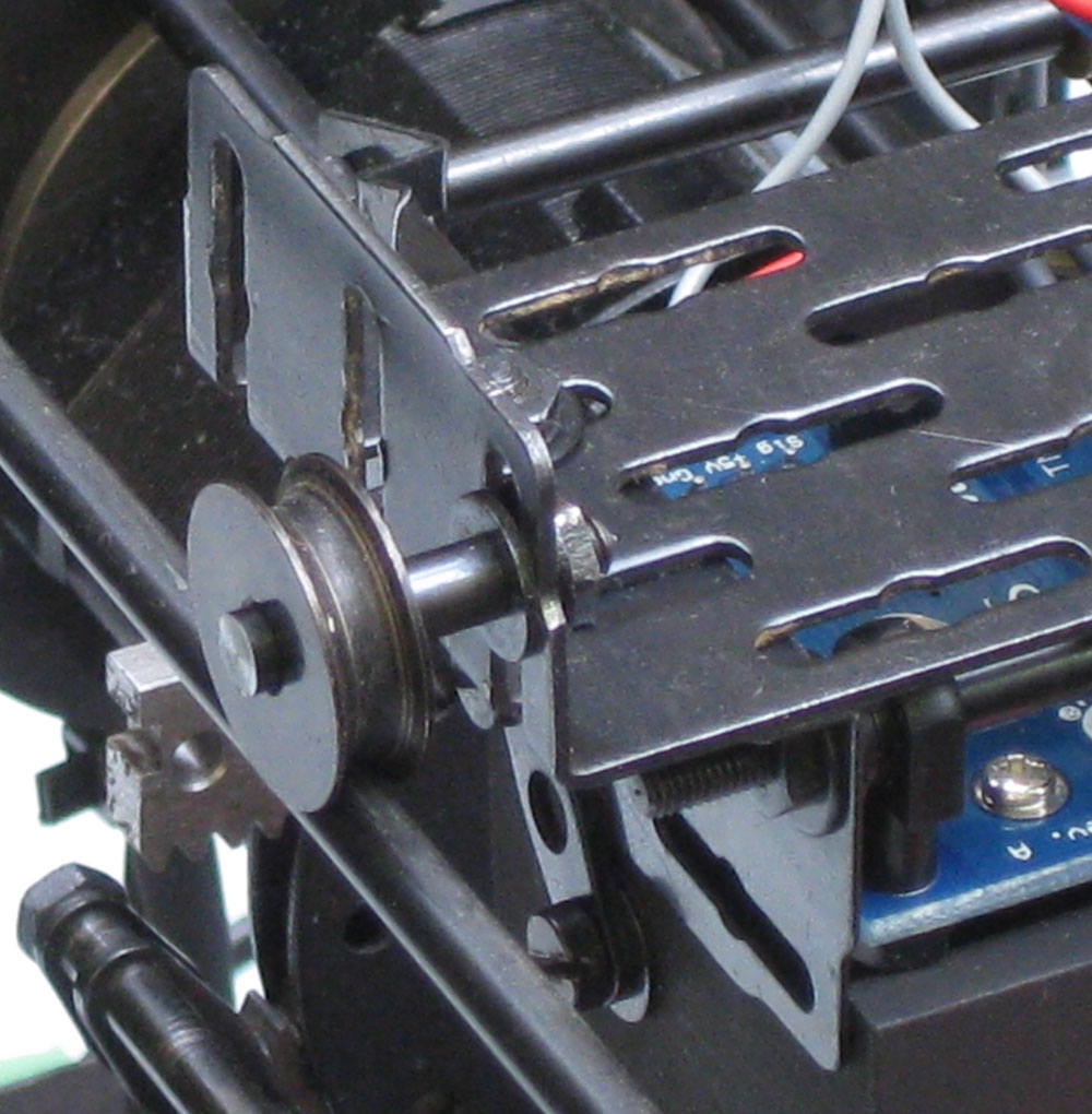
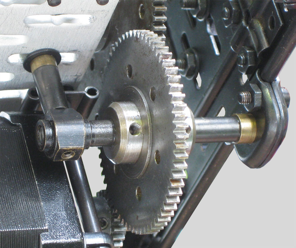
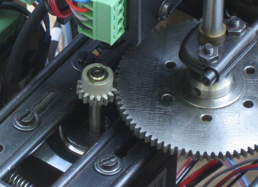
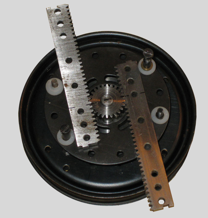
The toothed gearrack measures 4mm in thickness (currently the standard thickness of the gearracks sold by FAC is 3mm), which is equal to the diameter of the 4mm axle just above the rack. To avoid friction between the rack and the 2 flanged rims a piece of paper is placed between the rim and the 4mm axle. In this way just enough space is created for the gearrack to move freely between the rims.
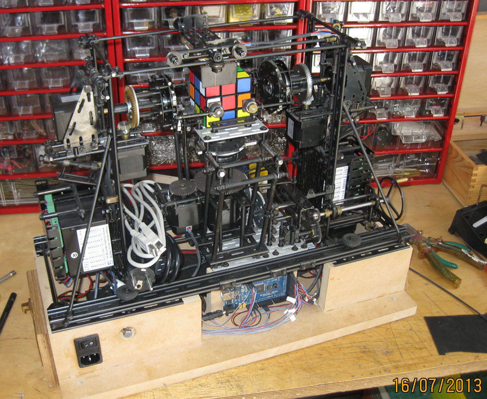
Technical difficulties regarding the color scanning proces and in writing code delayed the project for 2 years. Fortunately by the mid of 2013 the colordetection issue was solved and the solver was mechanically finished. The color scanner was made from simple analoge electronics: seperate RGB LED’s and LDR’s with well chosen resistors.
Final concept
Writing proper code and getting the machine work based on an intelligent solving algoritm proved to be a very challenging proces. It was not until I met the gifted programmer Maxim Tsoy early 2015 before a working model of the cube solver could be presented.
I have always been impressed by the Kociemba algoritm and we gratefully made use of his intelligent algoritm. The Arduino was for this reason substituted by a Raspberry Pi controller, the Compute Module to be specific. As a consequence to this decision we had to change the circuit of the color detection sensor. A more dept analysis of this proces can be found on the blog of Maxim Tsoy.
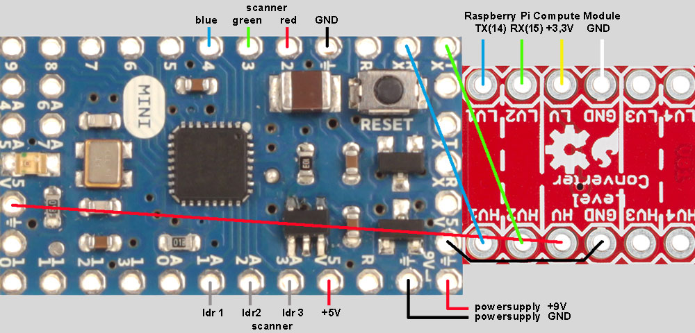
Eventually we used 3 modified Colorpal sensors to speed up the color detection proces. The analog readouts of the Colorpal are directed to an Arduino Mini, which is on it’s turn connected to the Raspberry Compute Module through a logic level converter.
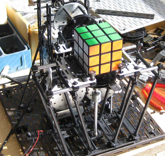
This configuration has led to a succesfull working machine in the Summer of 2015. The pictures below are from the final version.
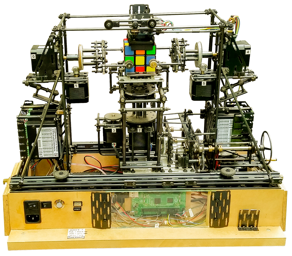
You only need to connect a powercable from the main power to the cube solver.
Color sensors
The cube solver uses 3 modified ColorPAL 28380 colorsensors from Parallax.
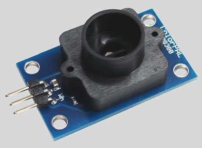
I like the compactness of this sensor and wanted to use them in any way possible. Unfortunately the Colorpal uses the BASIC Stamp language as an interface. This language is not supported by the Arduino or Raspberry program environment. So, making use of the Colorpals indicated, that I had to remove the onboard microcontroller and the EEPROM chip from the sensor. I added 3 new pins, connected to the RGB LED’s. The TAOS TSL13T light sensors were substituted by mini LDR’s and after some testing we managed to get very reliable readouts from these sensors.
At the bottom a protective cover was placed against the sensor with a row of black hair on the front and rear end in order to eliminate the ambient light.
Readouts of the sensor are processed by the Arduino Mini and directed to the Raspberry Compute Module through a Bi Directional Logic Level Converter from Sparkfun:
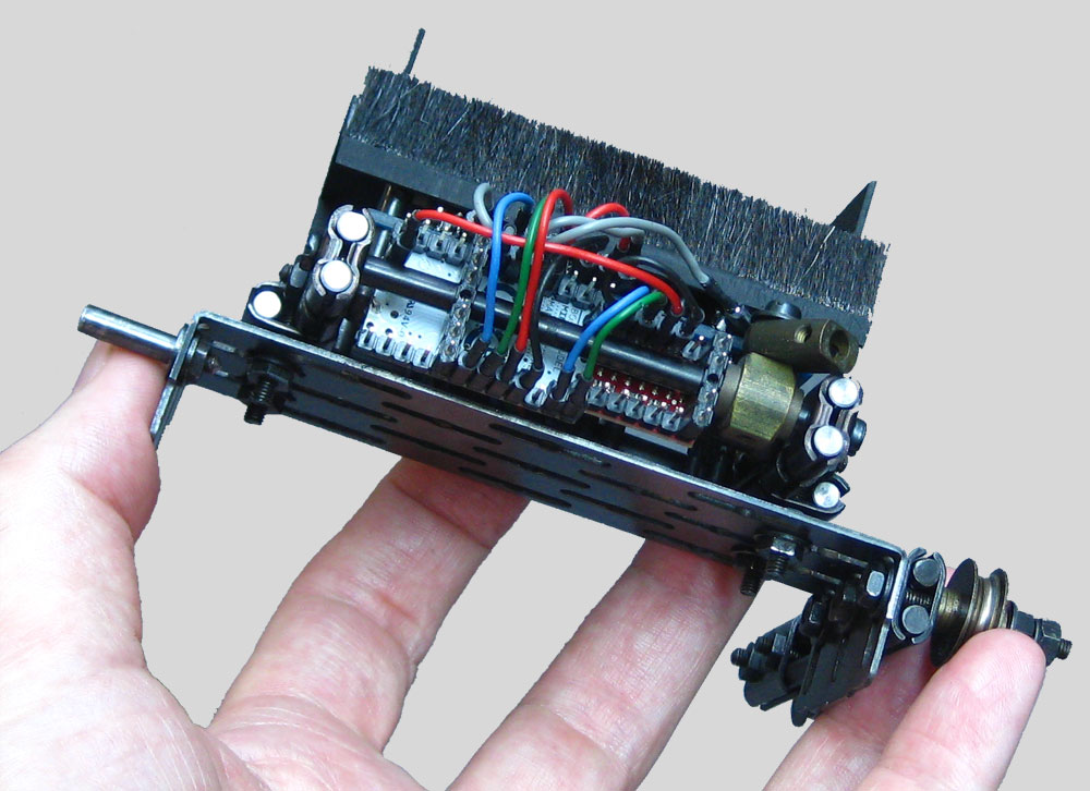
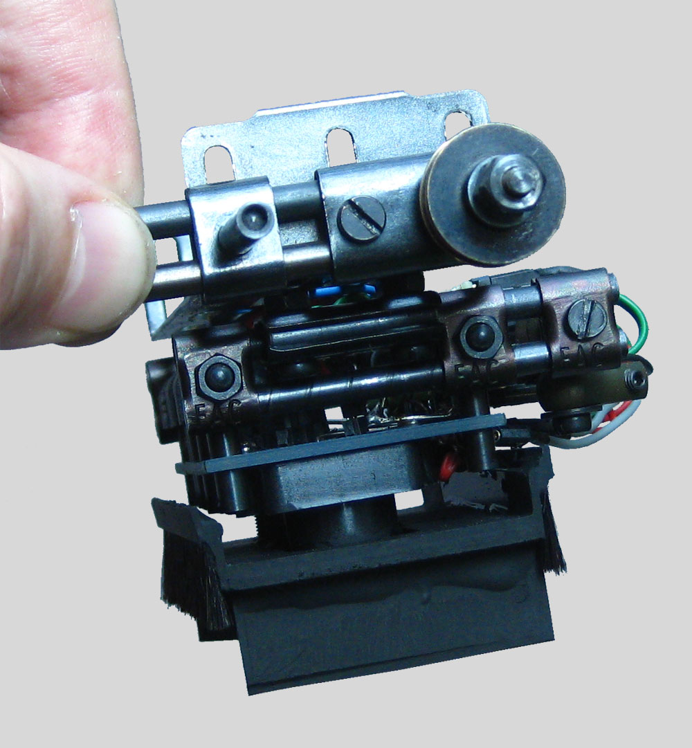
Finally, a few pictures of the sensor in my hand to get an idea of the size:
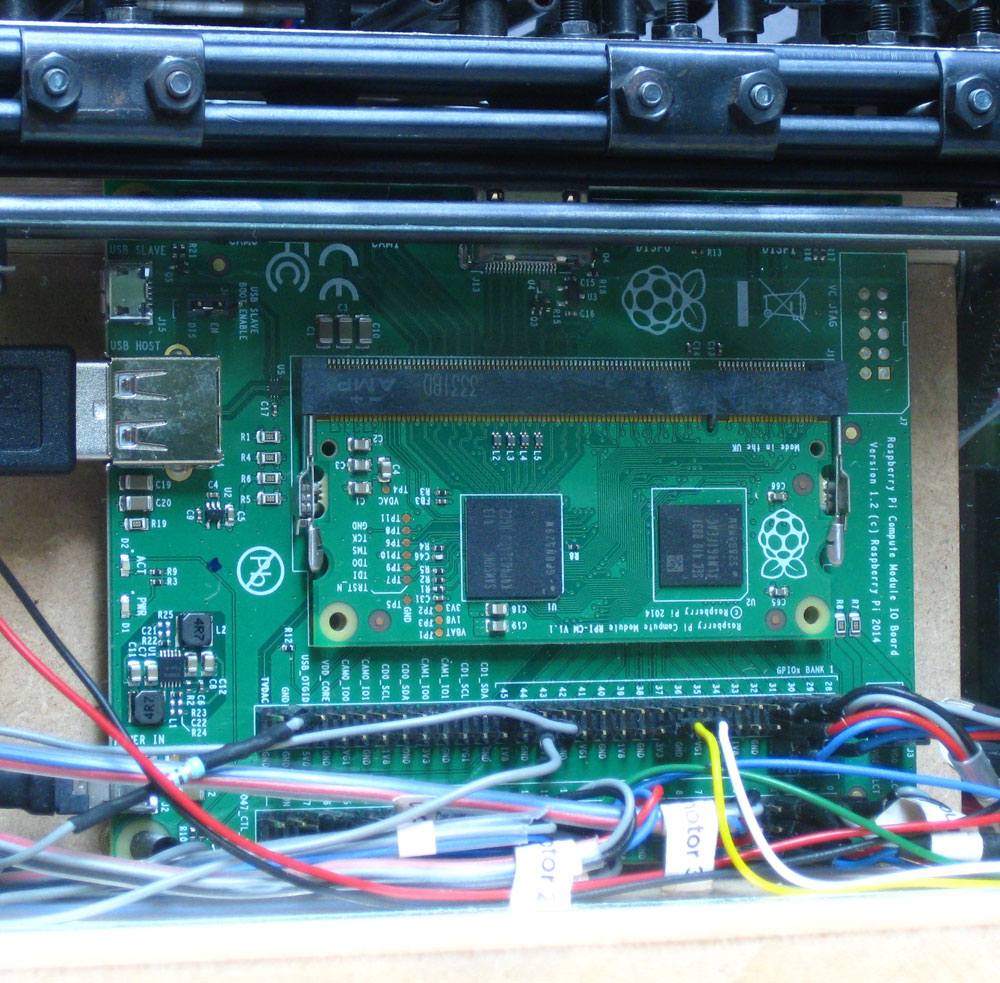
Controller board
The Raspberry Compute Module Board represents the heart of the machine.
Raspberry and Arduino are awesome tools for physical computing. These are open source microcontroller boards including a free software development environment. You can make interactive objects that can sense inputs from switches, sensors, and computers, and then control motors, lights, and other physical outputs like in the real world! More info about these tools can be found at the Raspberry and Arduino website.
The layout of the steppermotors and drivers can be found below. The dipswitches must be preset before operation and control the Ampèrage and the number of steps.