Meccano mechanisms
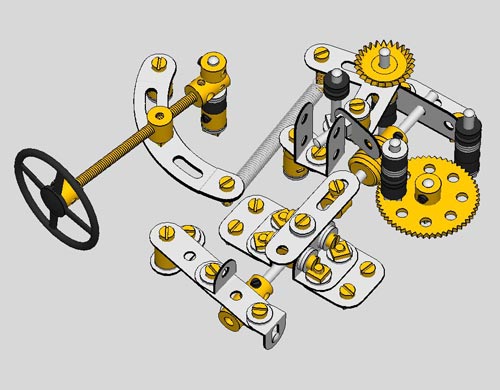
Rotary to linear mechanism
This device converts a rotary motion into a reciprocating motion. This device is straight from the (non Meccano) literature and works great. Unfortunately I didn’t make a video of this one.
This device was part of a modelstudy for a clock striking mechanism. The typical motion of the device was however not suitable for this purpose and was eventually substituted by the device as shown below.
Intermittant mechanism
This intermittant mechanism is used in MP 178.
See the video on my Youtube channel about the working of this mechanism.
Cardan gear mechanism

The mechanism translates a rotary motion into a straight line motion and is part of a drawing machine.
Click here to download the VirtualMEC model and see how it’s working.
With thanks to Pierre Monsallut who made a correct working model in VirtualMEC.
Special gear ratios
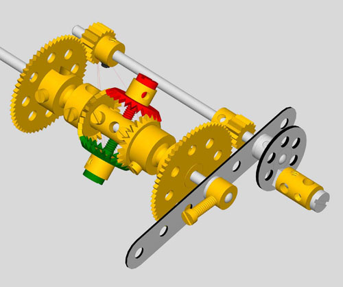 When facing the task of building a gear train with a reduction ratio unobtainable with standard Meccano gears, the problem can be solved by using a differential. The differential splits the desired reduction ratio in 2 terms, both of which may be achieved by means of availbale Meccano spur gears.
In the model above the following speedreduction of 7:24 was reached: 1/2 x (19/57 + 15/60) = 1/2 x (1/3 + 1/4) = 1/2 x (4/12 + 3/12) = 1/2 x 7/12 = 7/24
The crankwheel rotates 24 times whilst the satellite carrier output shaft will rotate 7 times.
Click here to download the VirtualMEC model and see how it’s working.
With thanks to Pierre Monsallut who made a correct working model in VirtualMEC.
Acceleration and deceleration mechanism
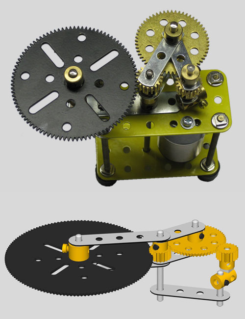
A 19t gear has been excentrically mounted on a motor shaft, in a way, that the pitch circle of the gear is exactly in the centre of the motorshaft.
the 57t gear and the following 19t gear work as an idler.
The gear on the motorshaft rotates with a uniform speed whilst the 95t gear uniformly accelerates and decelerates! This mechanism will be part of a drawing machine.
See the video on my Youtube channel about the working of this mechanism.
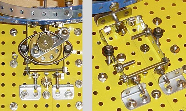
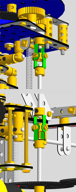
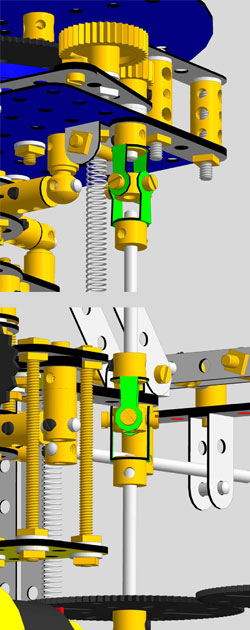
Correct and incorrect positioning of the forkpiece
Too often I see models on Internet or in magazines with an incorrect positioning of the forkpieces. The inner (or outer) forks of the couplings should be positioned in the same plane as shown on the left picture. The angle between the forks of the same coupling, can be considerable (for example 30 degrees or more) as long as this is the case for both couplings and as long as the input and output axle are in the same direction.
A good way to see what happens if you do this correct or incorrect is to test this setup in a car. Just see what happens when the angle is considerable (let say more than 10 degrees) when you drive the car on the floor.
In some cases I see examples of devices using only 1 coupling where as the input and output axle show a angular difference. This should be avoided too, assumed if you want smooth running devices. The input axle is driving with a uniform speed, but the speed of the output axle is sinussoidal within 1 full revolution. The amplitude of the sinus increases when the angle of both axles increases.
 CORRECT and INCORRECT positioning of the forkpieces