Electronics and Meccano
Parts of the content of this page is from 
Steppermotors, steppermotorcontrol, programming
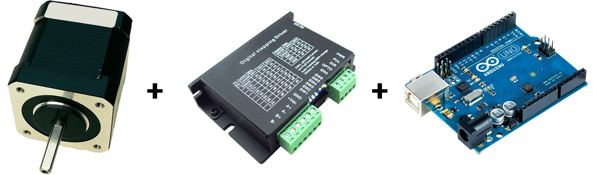
Above the three necessary components: a steppermotor, a stepperdriver and an Arduino program shield. The steppermotor and the programshield are connected to the stepperdriver, which is on it’s turn connected to a powersupply.
A stepper motor is a brushless, synchronous electric motor that converts digital pulses into mechanical shaft rotation. Every revolution of the stepper motor is divided into a discrete number of steps, in many cases 200 steps, and the motor must be sent a separate pulse for each step. The stepper motor can only take one step at a time and each step is the same size. Since each pulse causes the motor to rotate a precise angle, typically 1.8°, the motor’s position can be controlled without any feedback mechanism. For more dept information of how steppermotors work see Wikipedia. Whilst the rotational speed of a brushmotor or geared motor is defined by voltage control, the rotational speed of steppermotors is defined by the given number of pulses per timeperiod.
So regardless the (variable) load (within reasonable limits of course) connected to a steppermotor, the rotorposition will always show an exact rotational displacement per timeperiod. In other words: the rotorposition of a steppermotor is not defined by the parameter voltage or torque, but by the parameter time.
This makes a steppermotor very suitable for devices where synchronity between devices is an absolute condition.This was one of the reasons to substitute the 2 geared motors early January 2014 in my Boerdijk Super Meccanograph. I used an Arduino program shield, as Arduino is an open-source electronics prototyping platform based on flexible, easy-to-use hardware and software.
An easy to build bistable circuit
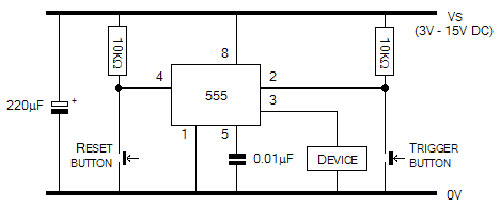 electrical diagram, the device can be a motor
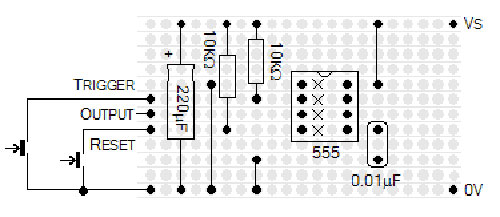 stripboard layout, the output is connected to the motor
shoppinglist:
- 1 x 0.01μF capacitor
- 2 x 10kΩ 0.6W resistor
- 1 x 220μF 16V capacitor
- 1 x 8-pin Dual-in-line IC Socket
- 1 x NE555N Timer IC (Standard 555)
- Stripboard SRBP (29 rows x 39 columns)
- (8 rows x 9 colums minimal required)
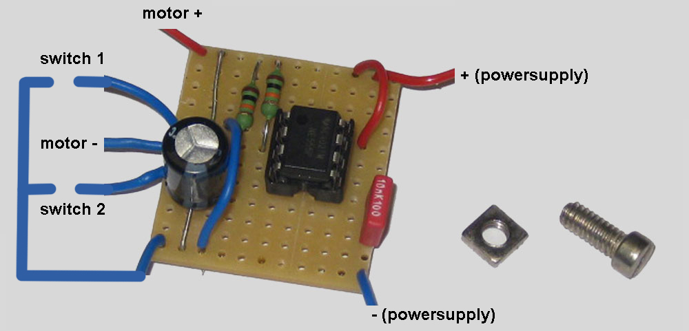 Bistable circuit, used for the Sinclair Harding Clock.