Dr. Ir. A. H. Boerdijk's Super meccanograph (available as model plan 182)
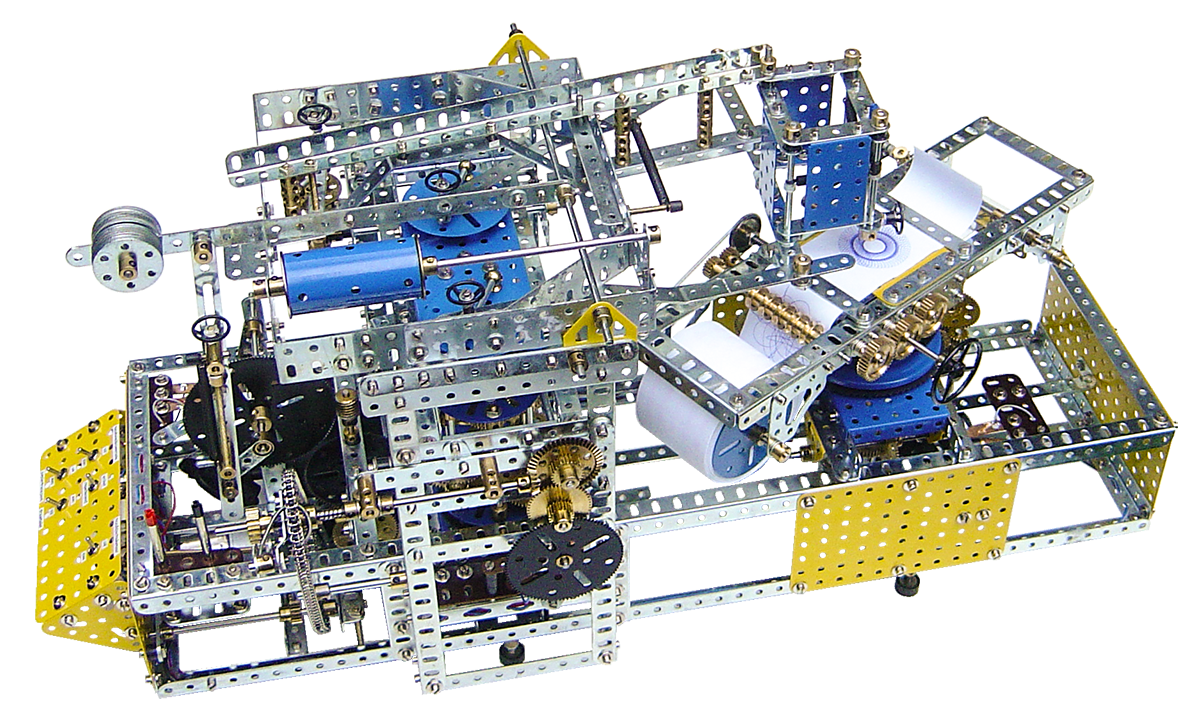
This famous model is based on the Super Meccanograph of Dr. ir. A. H. Boerdijk.
The original has been developed and built in the early 1960’s. After 1990 the Super Meccanograph was more or less lost out of sight. By the mid of 2007, research done by Wilbert Swinkels led to the tracking of this model.
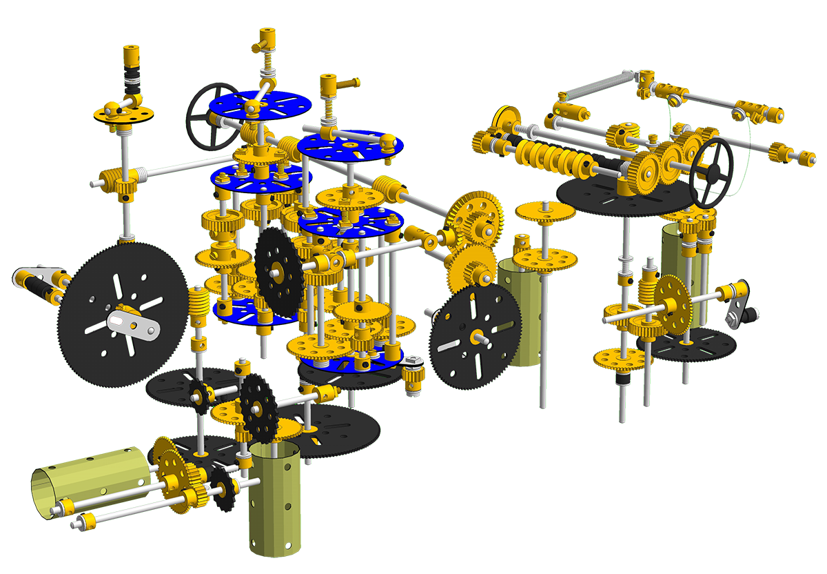
In the latter part of 2007 a replica was built and in January 2008 a computermodel in VirtualMEC was generated, based on the replica.
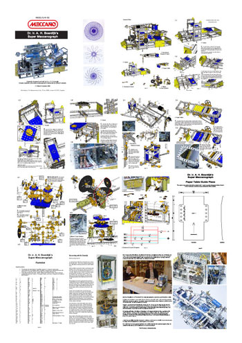
All of this has resulted in the making of Modelplan 182, available at MWMO.
Visit my YouTube channel Meccano Kinematics to view the working of this model.
In the past I have been contacted by a few Meccano friends giving me some very valuable feedback regarding MP 182. It’s likely, that more builders will cope with the same kind of questions and therefore I decided to publish some of these issues on this site.
Issues are:
- motors
- program and Arduino board for the stepper motors
- my opinion about the use of bent parts like strips and flat girders
- powersupply
- paperroll
- electrical switching and the position af several cranks
- ratchet device on the 36tooth sprocket wheel
- papertable
- 56t gear
- the Super Meccanograph as a 3D file
1. Motors
Motor M1, M2 and M4 run at 42rpm at 12vdc
Motor M3 runs at 10rpm at 12vdc
As mentioned on the CD, which is part of MP 182 it might have been better to use for M3 also the same rpm as M1, because synchronity between the devices driven by these 2 motors is absolutely neccesary to get satisfied drawings. The speed of these 2 motors (M1 and M3) have to be exact, because the devices actuated by these motors must run synchron. If not, the tip of the ballpoint does not end where it began on the paper, resulting in a drawing that looks not correctly finished. The best solution however is the use of steppermotors.
M2 and M4 run only within a limited time and these motors actuate the geardrums and the papertransport (they don’t have to be exact). It’s obvious, that these interactions must be finished before the pen is pushed downwards to the paper again to start a new drawing.
It must be mentioned, that the well known Meccano (Marx) M5 motor, which is by itself a wonderful piece of engineering, does not comply with the engineering requirements regarding the torque and maintaining synchronity. This motor can not be used as a substitute for M1 and M3.
I ordered the motors directly from Jameco, a USA based company, worldwide delivery.
Attention: after a close study at the current links (december 2013) regarding the Jameco motors, it became clear to me, that the specifications of the motors as sold by Jameco regarding the rpm parameter have been changed over time. For this reason I substituted early January 2014 Motor M1 and M3 for steppermotors and I can strongly suggest to use these type of motors, as they are commonly available and the rpm can be programmed and stored on a programmable shield like for example the Arduino.
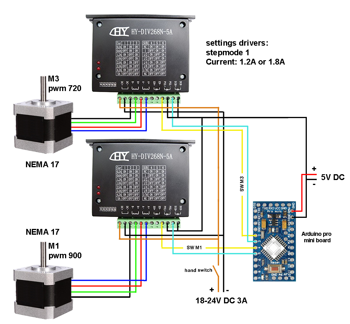
2 program and Arduino board for the steppermotors.
I used an Arduino Mini. The code to operate the steppermotors including the Arduino Mini is for sale at €15,-. As per 2023 I am only using TMC drivers for my projects. These drivers are socalled silent drivers and are absolutely phenomenal when it comes to practical and satisfying solutions. Whilst other drivers like the A4988, the DRV 8825 or the HY DIV 268N will do the job, they all cause the steppermotors to run with vibrations. These vibrations can be felt and heard in the entire construction of the model and it should be clear that this is an undesirable effect. The TMC drivers are THE solution to applications where steppermotors are implemented into mechanical devices. The TMC drivers are mindblowing good, super silent, cause no electrical noise and give a very smooth running steppermotor without any vibrations at all.
The Youtube video of my super meccanograph was uploaded more than 10 years ago, and the TMC drivers were not installed at that time, so the video doesn’t do justice when it comes to it’s smooth running operation.
Another major improvement is the design of a small PCB board, accommodating the TMC drivers, the Arduino board and other neccesary components to connect the steppermotors to the powersupply. There is no need anymore to describe an electrical diagram when it comes to run these 2 motors. You just connect a 18-30V DC (3A or more) and 12V DC (1A) powersupply to the board and 2 steppermotors. Once operating, the motors run perfectly synchron, even when the load fluctuates. You can obtain a fully functional, soldered, adjusted and tested board including the code for €75 or €50 if you want to do the soldering and adjusting the drivers yourself.
3 my opinion about the use of bent parts like strips and flat girders
I have used bent flat girders for the balance frame, making them unusable in another model. I do not demolish the meccanograph. It’s a wonderfull piece of mechanical engineering to be kept for the rest of my life. Therefore I do not bother to modify single parts to be used for this specific model. The reason for using bent parts within this specific construction are explained on the CD.
4 powersupply
I used an ordinary desktop powersupply with following system specifications: 5-15 volts, 3,6A, 220-240V. The powersupply has been adjusted to 12 volts DC. The powersupply for the stepperdrivers has been adjusted to 18 Volts DC, 3A is enough.
5 paperroll
The paperroll is of a topquality paper, available at any office supplier and I bought it here. The dimensions of the paperroll must be: 12mm inside diameter, 70mm outside diameter and 57mm width of the paper.
6 electrical switching and the position af several cranks
the diagrams on page 18 and 19 of the ModelPlan must be studied very well in order to understand the interactive working of the switches. In general, the crank mounted on the 133th axle does make 1 rotation per session. Each session consists of making 1 drawing and changing the gearratios of the penarm and feeding the paperroll.
The machine operates as following:
- Whilst drawing, the contacts 5.2A and 5.2B don’t make contact (in some pictures one will see a fifth contact, but this last one is of no use anymore
- Whilst drawing contact 5.1 (Motor 4, papertransport) and 5.3 (Motor 2, geardrums) is interrupted
- When a drawing is finished, this will happen: crank 62 in the front of axle 14a (see 4.3) pulls down the balance frame, thus lifting the pen from the table. After this the other crank 62 at the back of the same axle 14a (see 4.3) pushes against the contacts 5.2A and 5.2B. This contact maintains for about 6 seconds. This axis is running continiously and so is the papertable. At the beginning of this 6 second period Motor M4 and M2 starts running. The contacts 5.1 and 5.3 which were disconnected will make within this 6 second period contact!. This is neccesary, because the contacts 5.2A en 5.2B are after 6 seconds interrupted again and M4 and M2 must still run until the cranks related to 5.1 and 5.3 will disconnect the whole elecrical ciruit. The crank mounted on the 133th axle does make 1 rotation per drawing
- When this is done M4 and M2 stop running (thus the paper has been transported and new speedratios have been assigned to the penarms) and after a couple of seconds crank 62 in the front of axle 14a will move the balanceframe in opposite direction, thus downlifting the pen to the paper
- The machine starts a new drawing.
7 ratchet device on the 36tooth sprocket wheel
The ratched device was a feature I added (the original doesn’t have it), but at the end it became clear that it was of no practical use and therefore it has not been described in the MP.
8 papertable
To transport the paper I used a serie of 1/2’’ pulleys, nr 23a. During operation I noticed, that when the paper is running to it’s end, the roll sometimes isn’t transported correctly. I have changed this part of the table conform following picture. The 1/2’’ pulleys 23a must be token out and in stead of this part 142m must be placed around coupling 63. A short grub screw 69c must be used to fixate the coupling on the middle of the axle.
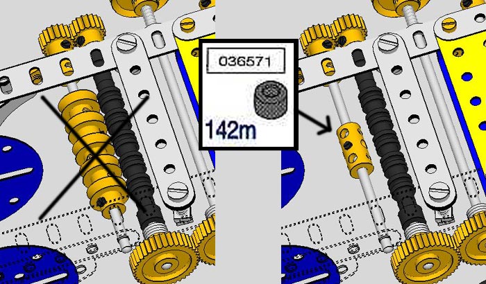
Please note, that neither Dave Taylor nor Frizinghall do sell this rubber tyre, but they use the partnumber as well! You can find this part in the official Meccano dealer partslist. The 6 digit code is a modern Meccano partnumber.
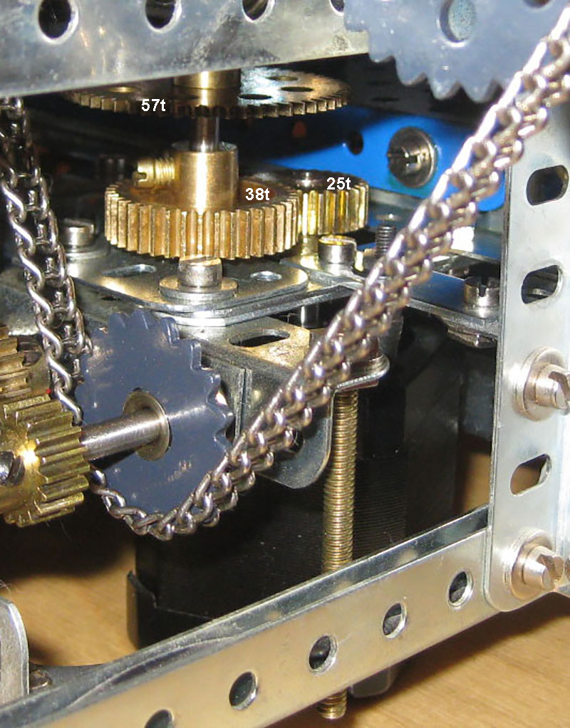
9 56t gear (now obsolete due to the steppermotors)
The 56t gear has initially been substituted by a 57t gear giving a perfect result of a drawn figure. It all depends on the speed of the motor under torque. More torque has an effect on the final speed and substitution of the 56t gear into the 57t gear was neccessary in order to keep synchronity between the papertable and the penarms.
Attention: as per january 2014 the motor connected to the afore mentioned gear assembly and the motor connected to the penarms have been replaced by NEMA 17 steppermotors. Therefore the 56/57t gear has become obsolete. The arrangement of the gears has been changed conform the following pictures:
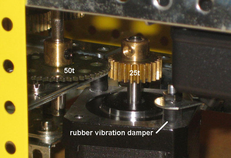 Assembly for M1 (papertable). As per 2023 I substituted the steppermotor drivers by TMC drivers. No more noise or vibrations. The rubber dampers on the picture are not necessary anymore.
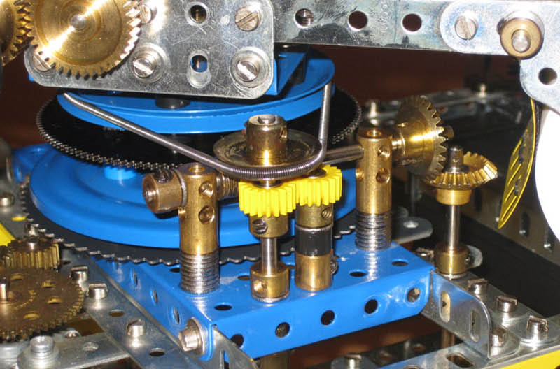 Note, that the worm gear is driving the papertable. I added the springcord to this assembly in a way, that the teeth of the 133t gear are continiously pushing against one side of the worm gear. The negative effects of the backlash of this gear assembly, sometimes caused by the movements of the drawing pen, is now eliminated from the drawing, whilst the papertable is running very smoothly without any vibration. I came to this insight after a close study of the drawings some time after publishing the MP.
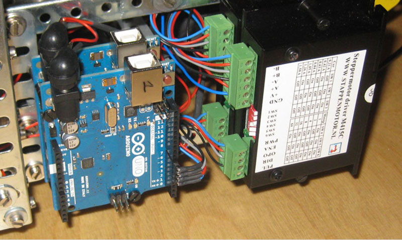 This is the prototype of the PCB. The final PCB is for sale here.
 Assembly for M3 (penarms). The rubber dampers are not necessary anymore, since the introduction of the TMC drivers.
10 the Super Meccanograph as a 3D file
The CD, which is part of MP 182 contains a digital file of the Super Meccanograph, called MP182.mdl. This file can be opened with the program called VirtualMEC, of which a demoversion is on the CD. With this file you can have a look at the Super Meccanograph in any direction. All it’s components can be studied separately as if it were sub assemblies.