Cyclographs Mark 4 and 5 by the brothers Tony and Maurice Rednall
Rednall cyclograph, Mark V
With special thanks to: Maurice Rednall, Tony Rednall, Meindert Buis
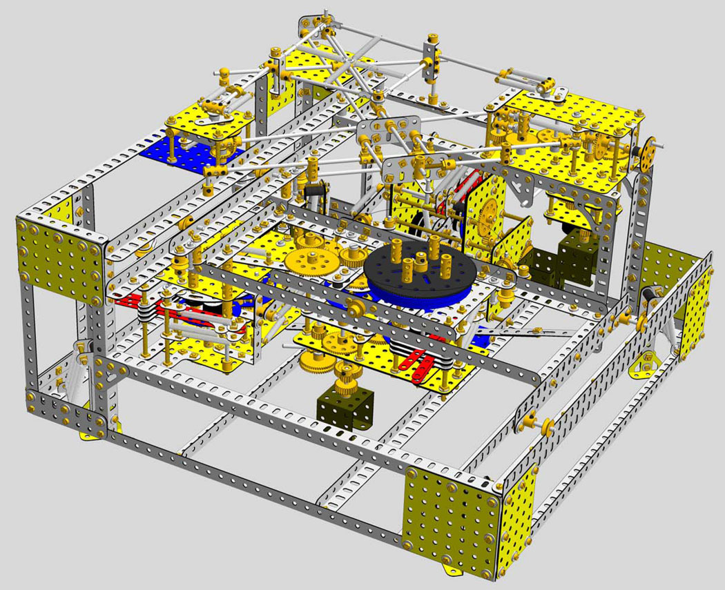
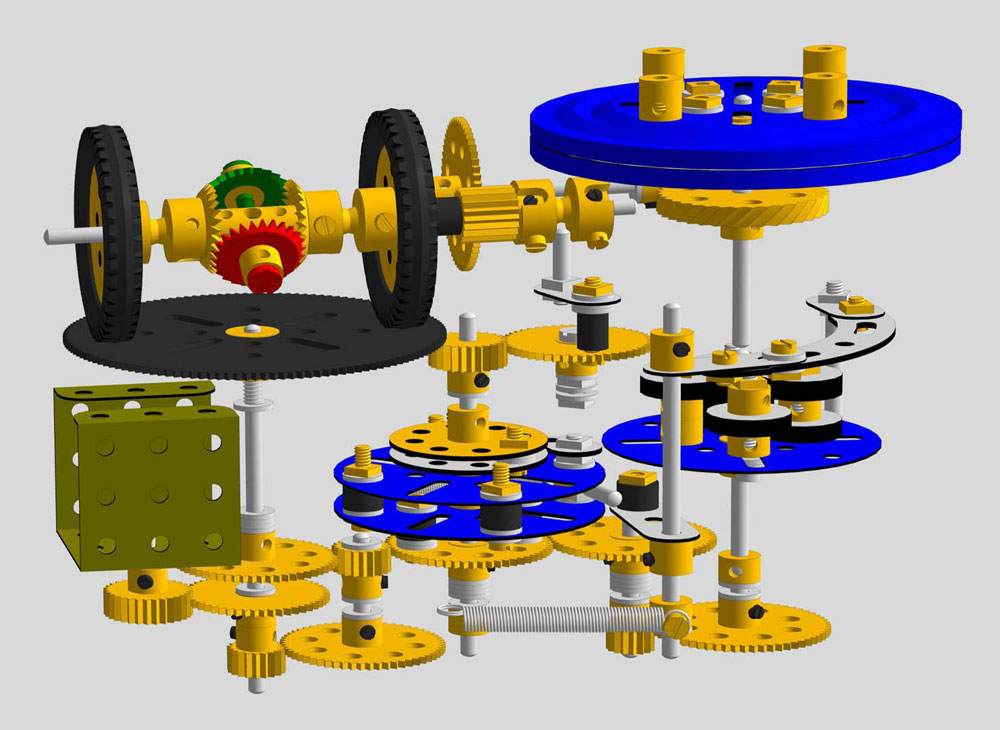
This model represents Mark 5 of the well known cyclograph, designed and constructed by Maurice Rednall. The 3D computermodel was made with VirtualMec, version 2.1.3 and can be downloaded here.
The first version of the cyclograph is after a design by Tony Rednall and has been extensively described in Constructor Quarterly nr. 14 of December 1991.
The first version fit to be shown in public was exhibited at Skegness in 1989. A Mark 2, 3 and 4 followed, the latter fully detailed appeared in Constructor Quarterly nr. 14.
The Virtual Mec model as shown on the left represents Mark 4 by Tony Rednall. Mark 5 is inspired by it’s predecessor.
The 3D computermodel was made with VirtualMec, version 2.1.3 and can be downloaded here or via the VirtualMec website.
Important notice regarding couplings: see under Meccano mechanisms.
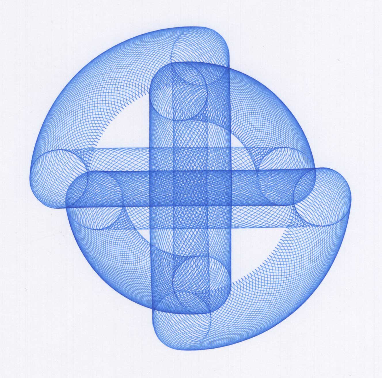
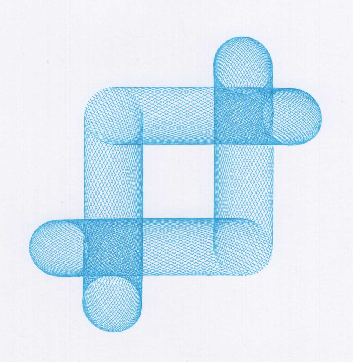
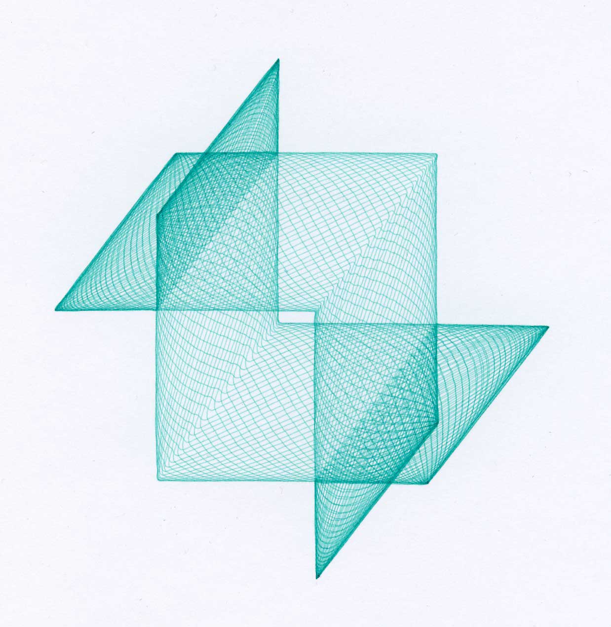
Below: pictures drawn by the Mark 4 (click the picture to enlarge)
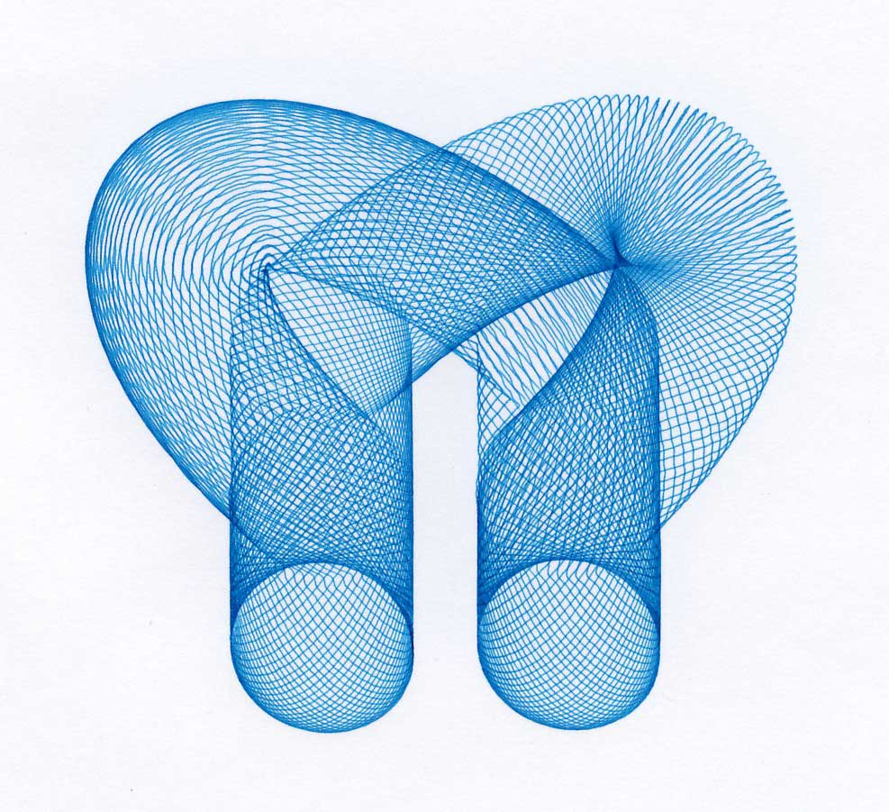
Photo’s with courtesy of Philippe Moerman
 The ‘heart’ of Mark 4.
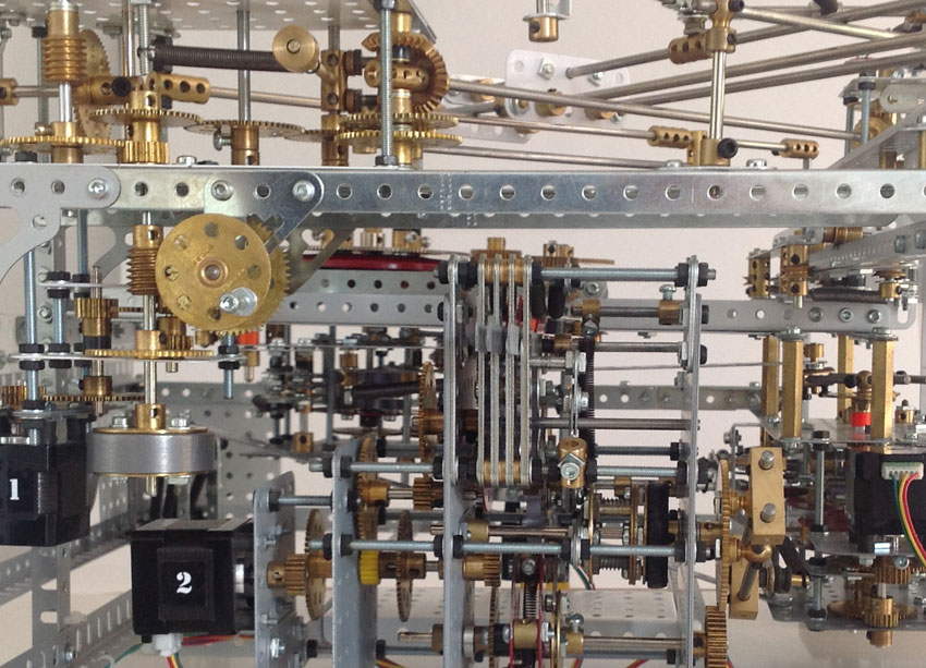
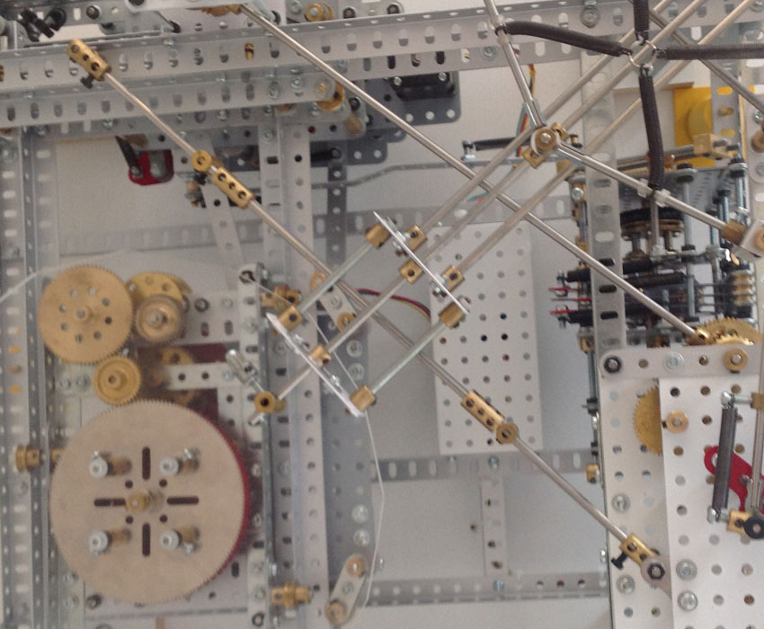
 The ‘heart’ of Mark 5.
I became very intriged by the design of the Mark 5, which firstly came under my sight in the summer of 2010. Between August 2010 and Mai 2011 I did have several times mailcontact with Maurice Rednall regarding the Mark 5 cyclograph. The main purpose was to develop a 3D VirtualMEC model from this cyclograph, so that other Meccano enthousiasts are able to build this impressive model themselves. Photos, specially from more complex models often give not enough information to reproduce a model in all it’s detail, at least not without any kind of feedback from the designers.
Thanks to the developers of VirtualMEC it’s possible to create 3D Meccano models regardless their size or complexity. A 3D computermodel can easily be exchanged over the mail without the need to create a timeconsuming ModelPlan. The following report are extracts of my communication with Maurice Rednall.
What is the difference between the Mark 4 and Mark 5 cyclograph?
The main difference is in the way the four basic motions (X, Y, table rotation and pen movement) are driven. In Tony’s machine (Mark 4) a single motor drove all four movements which caused many constructional difficulties resulting in a rather tall machine and a restricted drawing size. In my machine four identical stepper motors are used, one for each movement, which results in a much lower height but takes-up more room on the table.
There are 4 distinct movements controlling the pen:
- The pen pantograph over the table relative to the frame.
- The table movement under the pen in the X direction also relative to the frame.
- The table movement under the pen in the Y direction relative to the X direction.
- The table rotation under the pen relative to the Y direction.
These 4 movements must be kept in exact synchronism and in the Mark 4 machine this was done by using a single motor. From this motor each movement had a specific gear train. One will realize that the drive to the table rotation for instance must allow for the table to be moving in the Y direction and in the X direction at the same time. For this reason, the Mark 4 machine was provided with universal joints which had to be kept to small angles to avoid non-linearities, which is one reason why the machine was rather tall.
 Photo’s with courtesy of Meindert Buis
What type of motors are used?
All motors are stepper motors. Motors 1 (X), 2 (Y), and 3 (penarms) are 100 steps per full rotation (spr) operating in 1/2 step to give 200 spr. However, Motor 4 (table rotation) is 200 spr operating at 400 spr, which means that Motor 4 runs at half the speed of the other 3 motors. This explains why Motor 4 has to have a 30T (instead of 15T) on its shaft to compensate. In conclusion this indicates, that all motors can run with the same speed if the geartrain is changed accordingly.
Since motors 1 and 2 are both mounted on the frame and rotate at the same speed then a single motor could drive both the pens and the X crank clutch. I originally built the machine with this arrangement but in order to be able to vary the relative starting phases it was quicker and easier to have a separate motor that could be controlled from a button. Having had some experience with stepper motors I realized that if 4 motors were used and that they all ran synchron, much complexity would be avoided and there was no need anymore to use rotating shafts and universal joints.
More info about stepper motors, see here.
Did you use non Meccano parts?
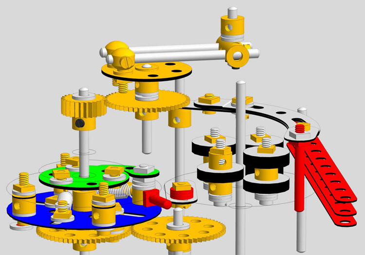
There are several non-Meccano parts especially in the gearing immediately beneath the table which provides smooth acceleration and deceleration to the table rotation.
All 3 clutches are identical in the way they function. The brass/nylon ‘collars’ were originally stacks of 3/4 inch washers (part 38d) but an undue quantity was required hence the substitution. They act as three, 4-lobed cams upon which rest the 3 selecting levers which are the cam followers.
The Cyclograph is very sensitive to the table being jogged hence the need for the spring suspension at the corners. Critical levelling is not required, in fact when running, the springs extend as the X and Y movements occur!
As for the gearing beneath the table, all non Meccano parts were substituted by Meccano parts and/or Meccano assemblies as shown below, which in the end result in a same kind of a moving characteristic. A working video of this particular mechanism can be found here.
Deceleration follows immediattely after acceleration and because of that this mechanism doesn’t provide a rotational movement with a uniform speed between the acceleration and deceleration moment to the turntable (133T) over more than 1 rotation.
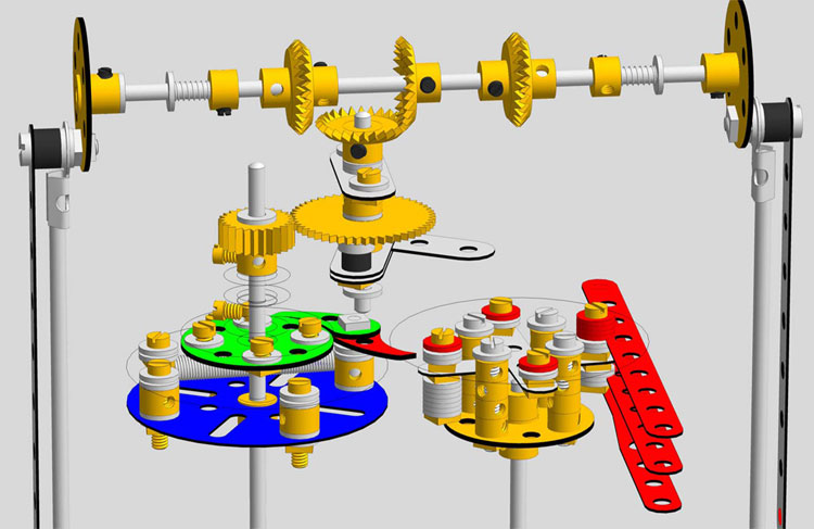
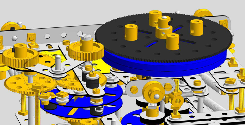 To achieve a uniform speed between the accelerating and decelerating over more than 1 rotation, the mechanism as shown below could work.
The idea is derived from differential analyzers and the driving is actuated by 2 in opposite rotating wheels driven by a wheeldisc (in this case a 133T gear) connected to a differential where as the inner shaft of the differential (63) is connected to the output shaft (blue roller bearing = turntable). If the distance from each differentialwheel relative to the centre of the wheeldisc is equal, the turntable will not rotate. However, when the palletpin, mounted on the 50T Exacto gear pushes the H-coupling to the left, the differential with the 2 rubber wheels is being pushed to the left as well and the wheels are now placed excentrically relative to the wheeldisc. During the afore mentioned operation the turntable starts to rotate from a zero speed to end speed quadratically, thus accelerating and keeps on rotating with an uniform speed.
Once the faceplate starts to rotate for a full revolution again, the differential is pushed back into it’s centre position and during this operation, the turntable is decelerating and finally stops rotating. Only when the faceplate rotates for 2 full rotations directly, the turntable shall respectively start to rotate, accelerates, decelarates and finally stops rotating.
The mechanism as shown above is based on friction between the wheels and wheeldisc and this is the weak part of the mechanism. Every slip from the wheel relative to the wheeldisc will affect the correct working of the turntable. Nevertheless, it’s an interesting mechanism and it’s reliability can only be proven if it is tested.
The 3D computermodel of the mechanism as described above can be downloaded here.
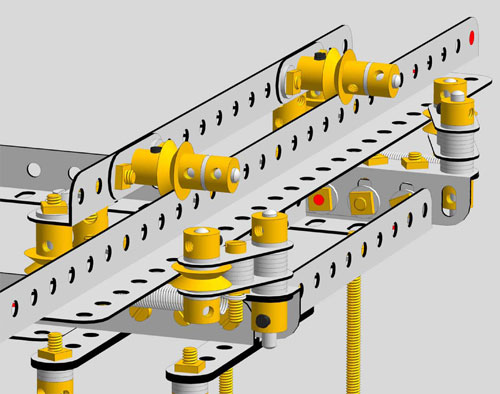
The sliding mechanism in the VM model is assembled with standard Meccano parts, but in practice the functionality of this specific assembly proved to be rather dissapointing.
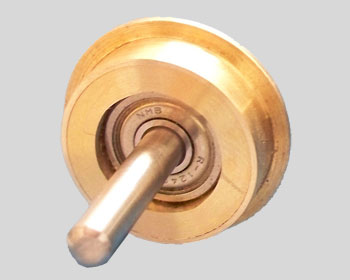
The flanged wheel (20b) is from Exacto (machined in stead of pressed). The boss has been removed by a lathe and replaced by a high quality roller bearing. This assembly proved to be usefull as a substitute for the Meccano parts as used in the left pictured sliding mechanism.
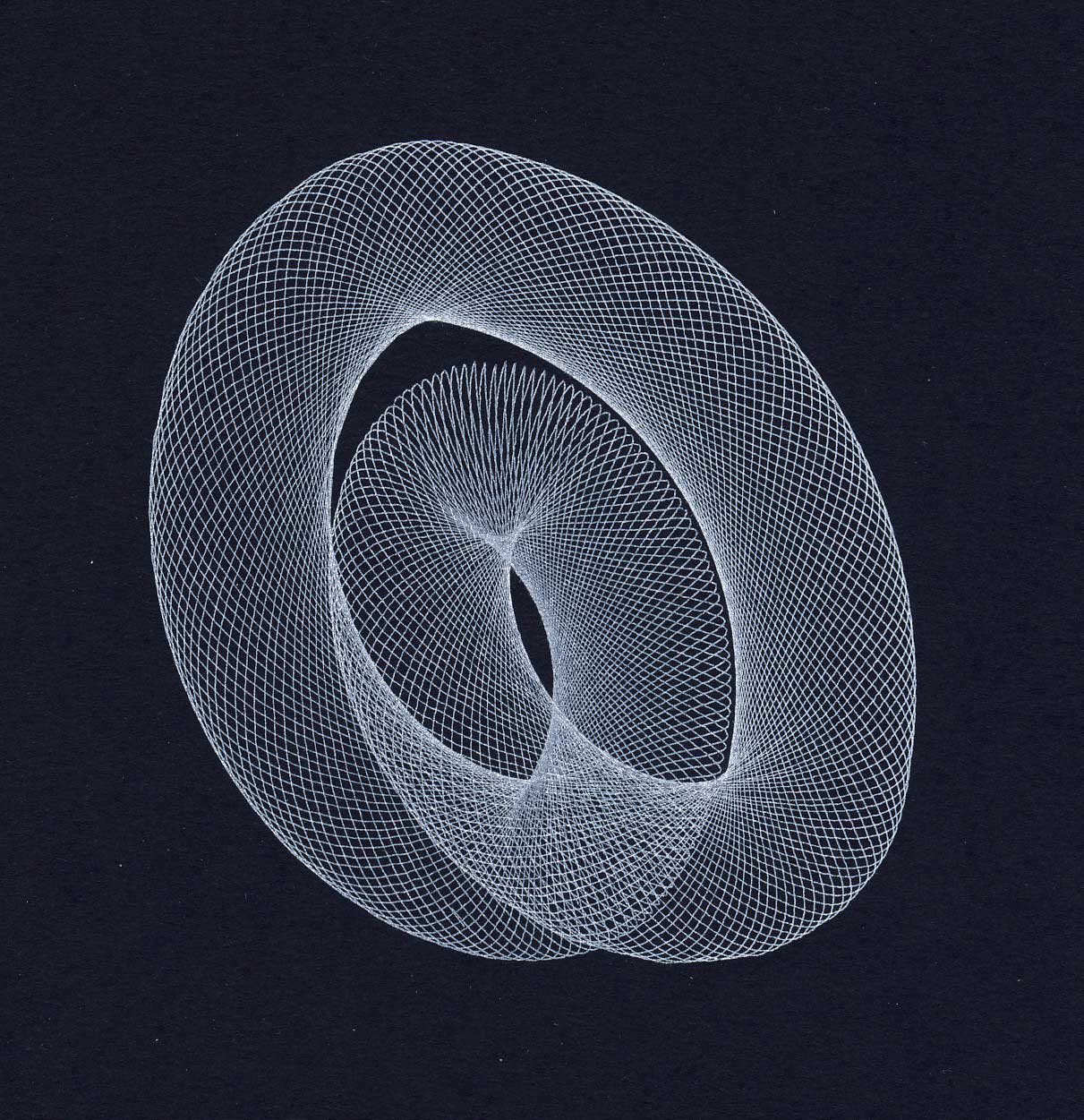
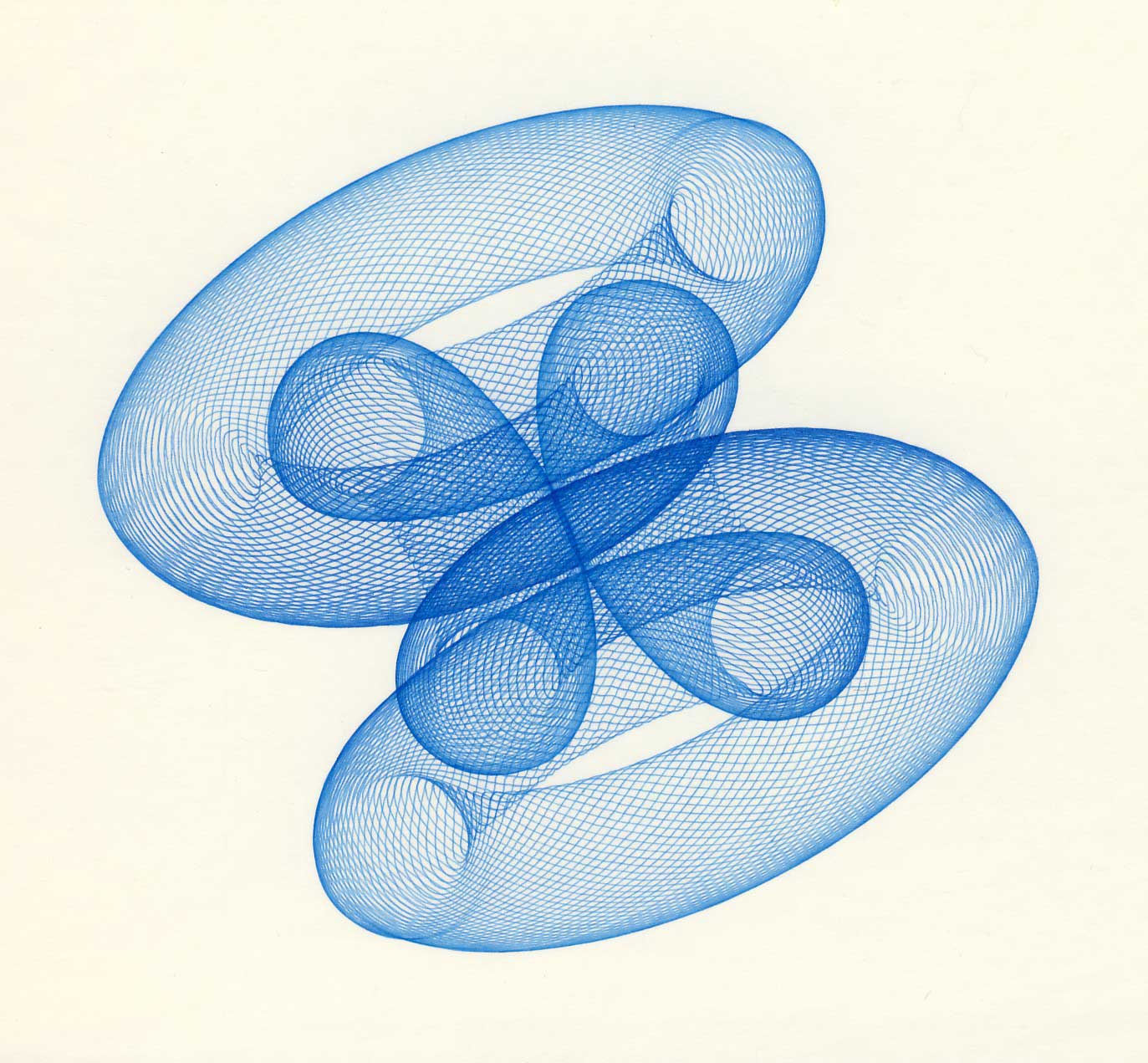
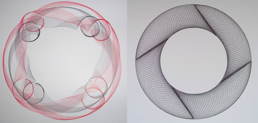 Pictures drawn by the Mark 5 (photo’s with courtesy of Meindert Buis)