FAC system 4 gripper Rubik's Cube Solver
Contents
- Overall design
- Gripper design and gripping performance
- Final contraption of the gripper component
- 2 Axis gimbal mechanism
- Autotron july 10 and 11, 2021: exhibiting the 4 gripper FAC solver for the first time
- Controller board, programming and overall schematics
Overall design
After finishing our first FAC system Rubik cube solver back in 2015 we decided to make a 4 gripper solver in FAC as well, but not before we made a 3 gripper Rubik cube solver in Meccano first. After finishing the Meccano solver the mechanical design of the 4 gripper protoype was more or less ready by the mid of 2016. Making a nice oak woodcase and incorporating all the mechanical components, electronics and hiding all the wires was done by the end of 2018. The programming part started more or less the same time. During the programming the gripper mechanics had to be modified a couple of times in order to achieve a reliable gripping performance.
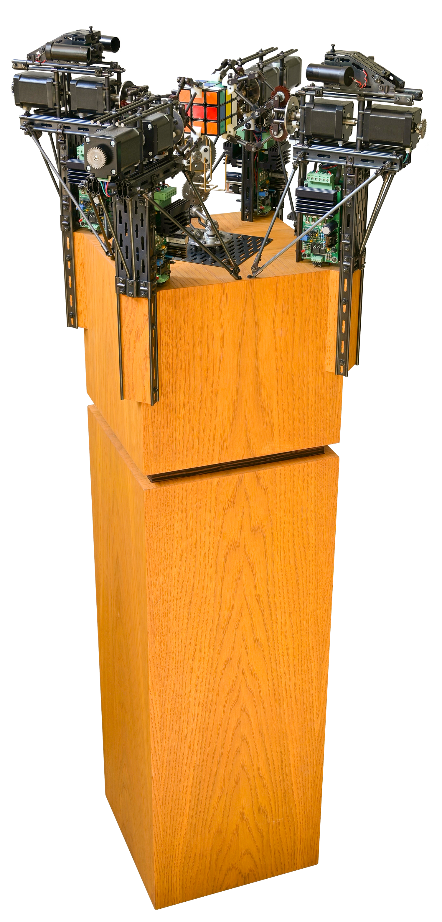 Overall view of the entire machine as per april 2021. The bottom part of the oak case contains the main power supply and the upper part contains all the electronical equipment like the compute module, microcontrollers and wiring. The electrical connectivity between the afore mentioned parts is made by a 14pin terminal block. This makes transport of the machine in 2 parts possible and the setup time at exhibitions is less than 5 minutes.
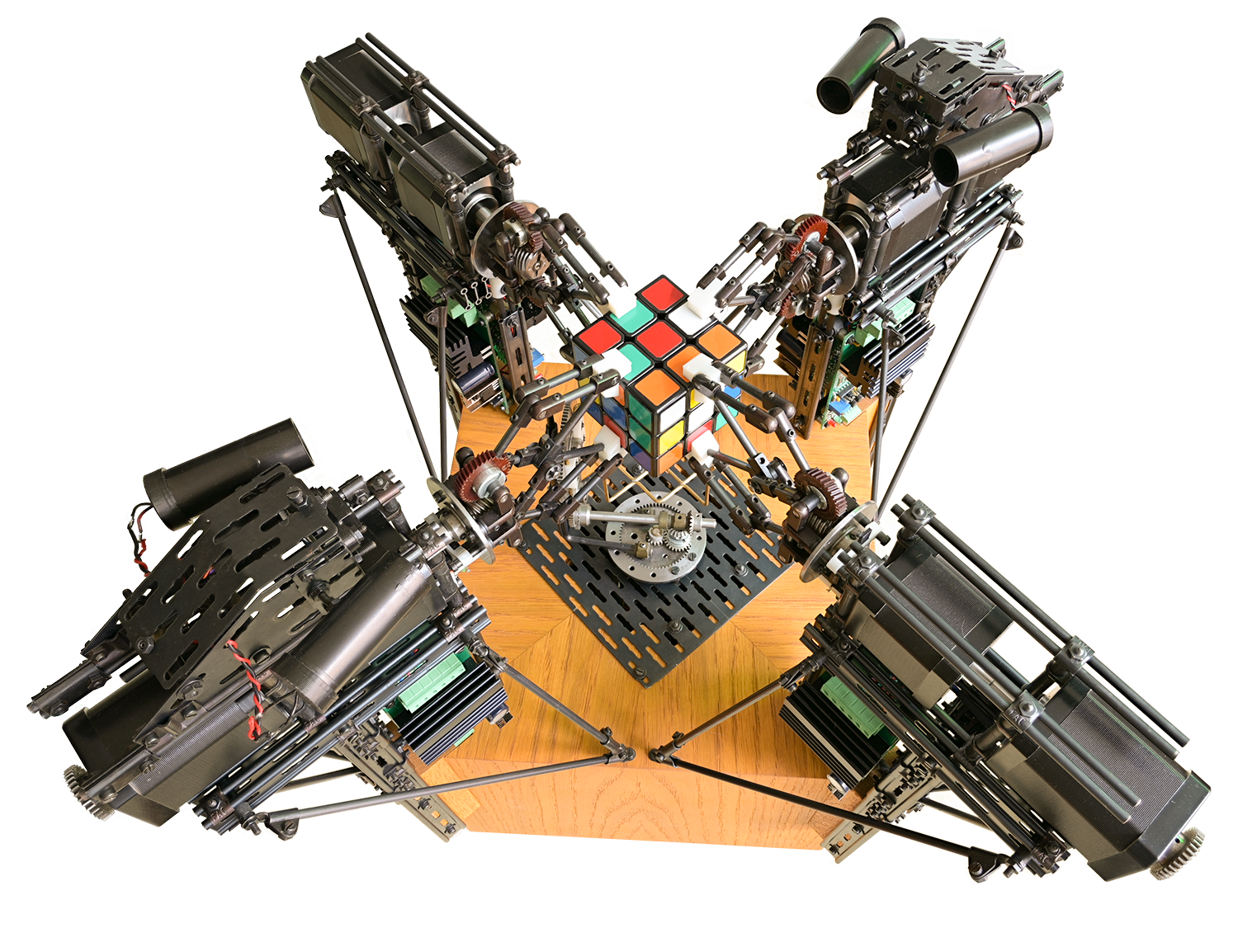 Cube solver as per april 2021
Gripper design and gripping performance
The grippercomponent has been entirely redesigned compared to our 3 gripper solver. Initially I followed the old school method to define the designparameters of the linkage diagram. A learnfull process, but quite time consuming.
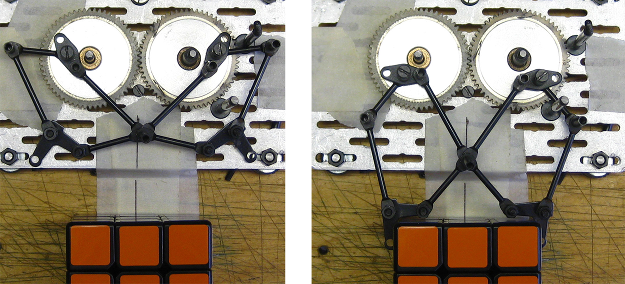 Old school prototyping of a linkage based gripper (july 2015)
After having set the designspecifications I designed a complete gripper system in AutoCad to be sure there are no desigflaws left and to assure the freedom of movements -gripping and rotating- of each seperate gripper.
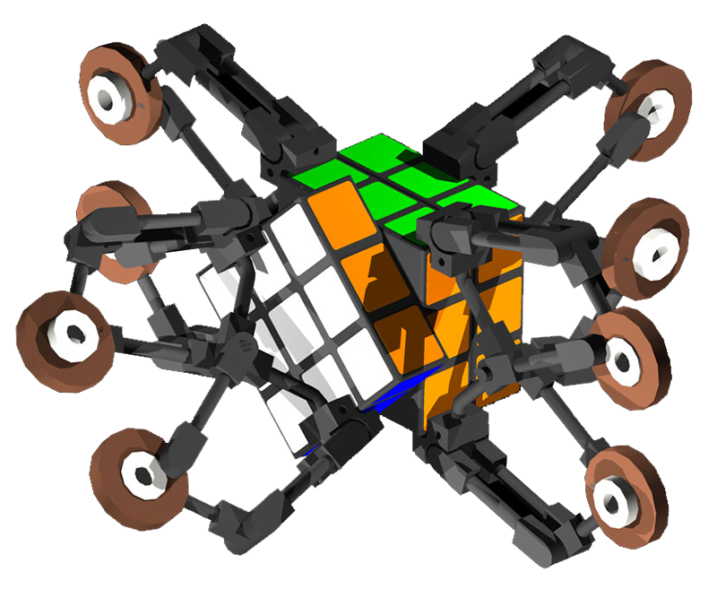 A digital study to check for designflaws
During testing in the real machine it became clear, that the gripangle was a bit unfortunate resulting in a less effective gripping performance. The gripper had to be modified, but I didn’t want to change it conform the method of the old school prototyping. Searching on Internet for a good linkage mechanism design software I came across the linkage program of David Rector. With this package I was able to finetune the parameters of the gripper mechanism resulting in an optimal performance of the gripper as a whole.
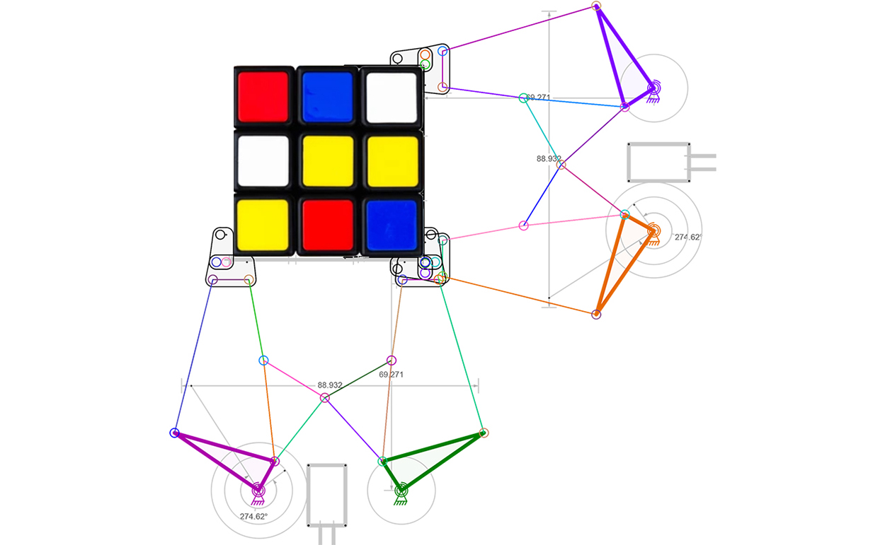 Prototyping a linkage based gripper With linkage design software (february 2020)
Initially grippertips were made in black coloured PETP (also known as Arnite), but the final grippertips, based on the latest insights regarding gripping performance were made with a 3D printer. Between the grippertip and the cube low density rubber of approx 2mm thickness has been used to achieve a firm gripping.
Final contraption of the gripper component
The oak basement is used to mount all the grippers. It’s obvious, that precise dimensioning of the oak basement is important, but within each gripper component there are sufficient adjustments possible when it comes to a precise positioning of the gripper relative to the cube.
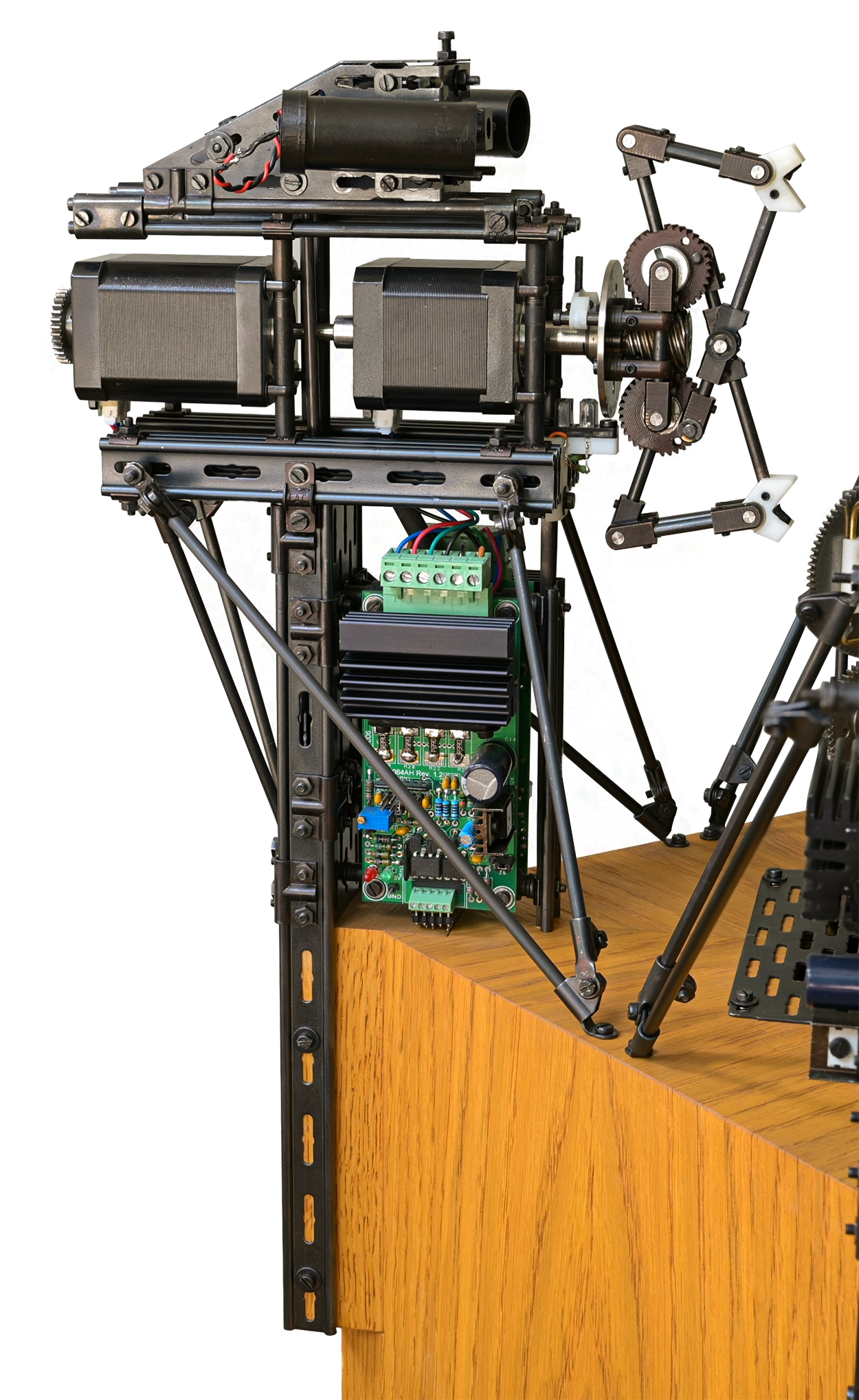 Each gripper component is attached to the oak base and kept in position with 4 long screws. The wiring leads through the oak into the upper compartment of the oakbase. On top of 2 out of 4 grippers an extra carriage for the pi camera is installed together with 2 lighttubes, accomodating powerled’s.
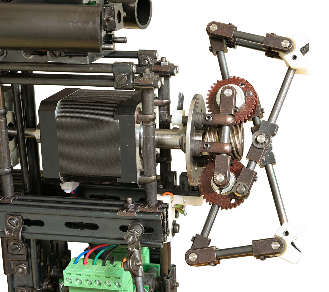 Some parts are custom made like the grippertips, the carriage of the IR sensor and the disruptorshield mounted at the rear of the flanged wheel. The afore mentioned parts are all 3D printed in ABS. The IR sensor is used for homing the gripper into a predefined position. The steppermotors are attached to the framework by using FAC system parts only.
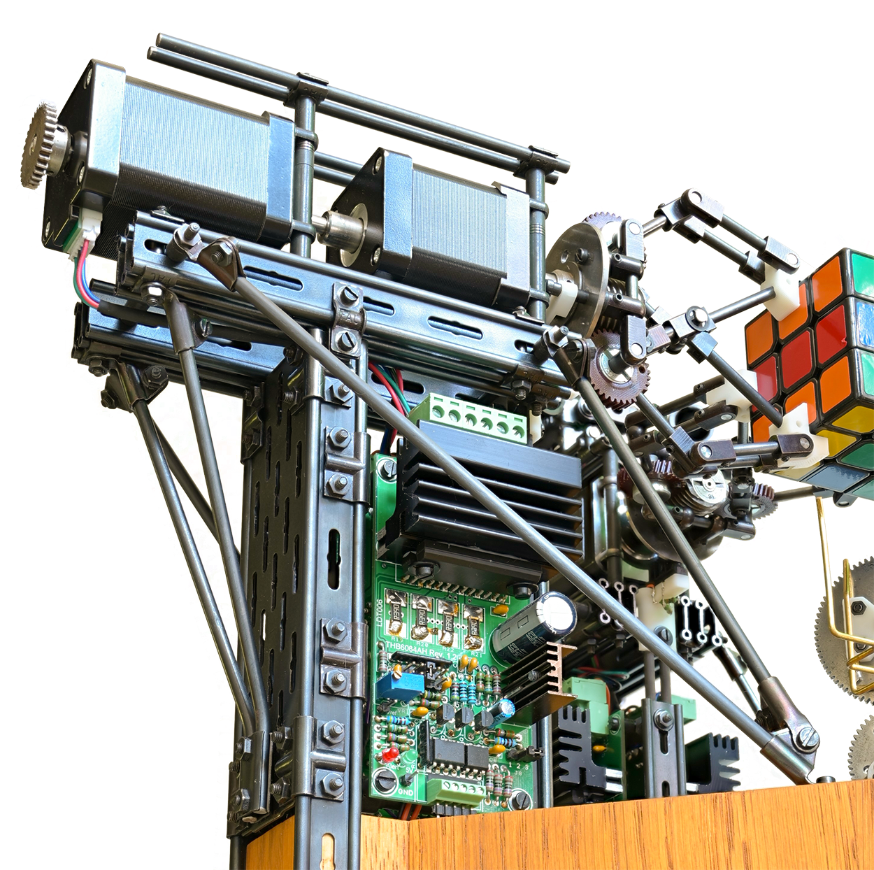 Rods were used to make rigid structures in multiple directions to avoid any possible deformation during operation. The stepperdrivers are designed by Luc Degrande and are available as a kit.
2 Axis gimbal mechanism
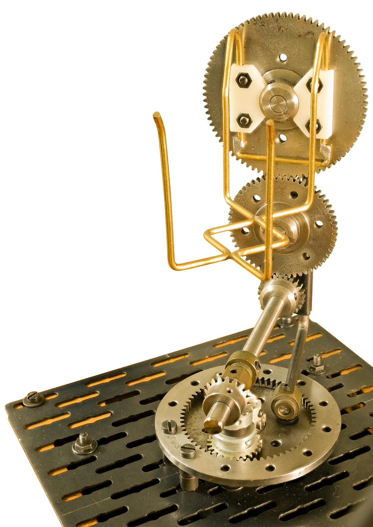
This is probably my favourite part regarding the mechanical design. The 2mm brass wire to hold the Rubik’s cube and the white 3D printed blocks to keep the brass wire firmly attached against the gear wheel are the only non FAC system parts in this contraption. The mechanism is actuated by one steppermotor and when running, the cube is being rotated into 2 directions at the same timne: 45 degrees on the pan axis and about 35 degrees on the roll axis. A second steppermotor will lower or rise the entire platform to which the mechanism is mounted on. To put it in other words: the cube is being altered from the camera position into the gripper position.
Autotron july 10 and 11, 2021: exhibiting the 4 gripper FAC solver for the first time
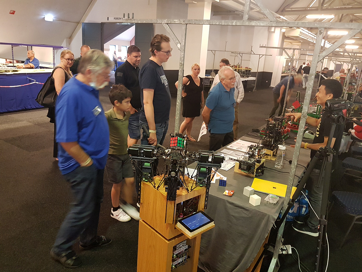
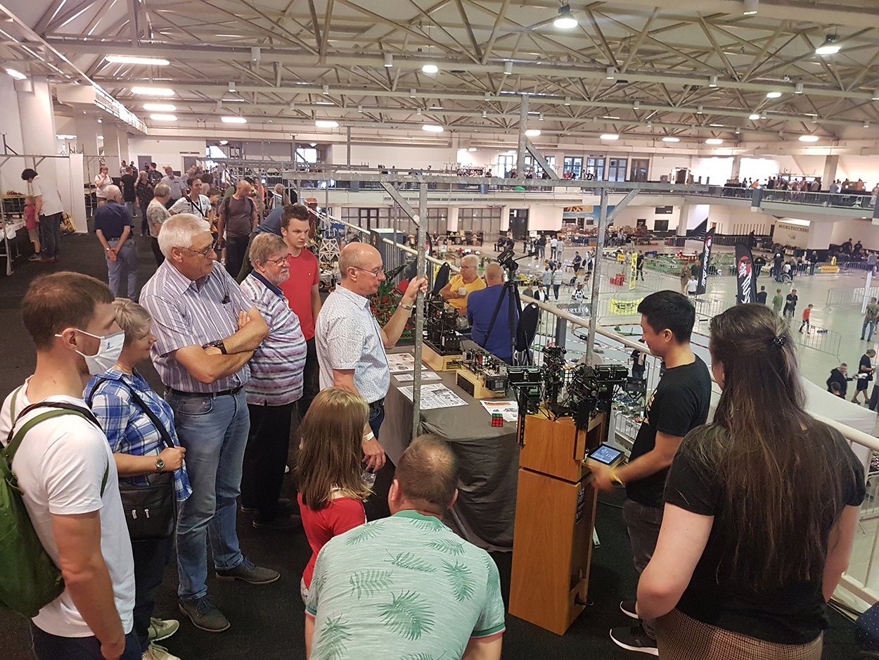 No complaints about the level of attention!
Controller board, programming and overall schematics
The Raspberry Compute Module Board represents the heart of the machine.
Raspberry and Arduino are awesome tools for physical computing. These are open source microcontroller boards including a free software development environment. You can make interactive objects that can sense inputs from switches, sensors, and computers, and then control motors, lights, and other physical outputs like in the real world! More info about these tools can be found at the Raspberry and Arduino website.